62
THE MATERIAL-FEED SYSTEM (CONTINUED)
HYDRAULIC SYSTEM
Hydraulic power for the Material Blower is generated by a fixed-displacement hydraulic
pump that is driven off the engine auxiliary drive. The pump receives hydraulic fluid from the
25.5-gallon (96.5 L) reservoir through a service ball valve and suction hose. It is then delivered
to the hydraulic manifold through an unloading valve. This hydraulic manifold block has three
separate solenoid valves that control all of the functions of the Material Blower machine.
The hydraulic oil should be replaced per the lubrication schedule or if the oil becomes milky
or gives off a burnt odor. The hydraulic oil filter must be replaced on schedule with a 5 micron
absolute filter.
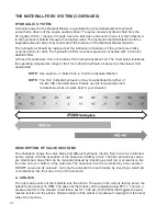
At time of manufacture, this unit contains Finn Vulhydra hydraulic oil. The chart below illustrates
the operating temperature range of the Finn Vulhydra hydraulic oil as well as the closest ISO
equivalents.
NOTE:
Use equal to, or better than, a 5 micron absolute filtration.
NOTE:
The Finn Vulhydra hydraulic oil may be substituted for either of
the two ISO oils listed below. Please use the temperature chart
to determine what oil works best in your situation.
DESCRIPTION OF VALVE SECTIONS
The illustration shows the valve block and different hydraulic circuits. Each circuit is controlled
by two valves, with the exception of the hose reel (middle) circuit. The floor and airlock valves
are directional valves that can be manually stroked by inserting a small rod or screwdriver into
the hole on top or bottom of the solenoid. The hose reel circuit is controlled by a two-position
ON/OFF valve and its solenoid can only be actucated in one direction by inserting a small rod
or screwdriver into the hole on top of the solenoid.
A. AIRLOCK
The right valve section of the manifold runs the airlock. The spool in the valve is factory-set so the
airlock turns at about 16 RPM. The speed of the Airlock can be adjusted using PFC-1. There is a
pressure switch on the forward circuit that is set for 1,500 psi (10,342 kPa) that triggers the auto-
reverse function on the airlock. Normal rotation of the airlock is clockwise if viewing from the driver
side of the machine.
Summary of Contents for A2548-001
Page 4: ......
Page 75: ...69 THIS PAGE LEFT BLANK INTENTIONALLY ...
Page 82: ...76 Lubrication Chart Top View of Unit 1 3 2 9 1 12 16 14 6 17 10 8 15 5 7 4 11 1 1 13 5 3 4 ...
Page 84: ...78 FINN MBH6 MATERIAL BLOWER TECHNICAL SPECIFICATIONS 166 78 31 57 67 91 97 86 ...
Page 86: ...80 NOTES 80 ...
Page 106: ...MBH6 MR1108 Rev A 100 WHEN ORDERING PARTS BE SURE TO STATE SERIAL NUMBER OF MACHINE 4 2 5 1 3 ...


