64
THE MATERIAL-FEED SYSTEM (CONTINUED)
HYDRAULIC CONTROL SYSTEM
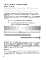
The hydraulic control system is an electrical system that controls all the hydraulic functions
on the Material Blower. This 12-VDC system runs off the engine electrical system. It is a
programmable logic control (PLC) system located in the main control panel on the passenger-
rear side of the machine. This module controls the solenoid valves in the hydraulic system. The
solenoids are energized by way of the Deutsch connectors mounted on each solenoid.
When the
FLOOR
softkey on the control panel or the
MATERIAL FEED
toggle switch on the
radio remote transmitter is activated, the proportional solenoid on the airlock valve section is
energized, which starts the airlock. The floor and feed roll solenoid is energized automatically
after a factory-set 2 second delay. This delay ensures that the airlock has a chance to clear itself.
After the delay, the floor and feed roll will begin to move at the speed relative to the Floor speed.
This speed can be set by using the floor increase and floor decrease softkeys on the control
panel or the floor speed dial on the radio remote transmitter. Pushing the
FLOOR
softkey on the
control panel allows the operator to temporarily turn off the floor to clear out the airlock.
As material drops into the top of the airlock, the pressure required to cut the material is monitored
by the pressure switch. This switch is located on the forward port of the airlock valve section, in
the manifold labeled PS-2 (see the Valve Block illustration). The switch is normally open. When
the airlock motor stalls due to the rotor encountering an object it cannot cut, high pressure is
created in the airlock circuit and the pressure switch closes. The amount of time the pressure
switch is closed is monitored by a setting in the PLC box. If the switch remains closed for more
than 0.5 second, the system automatically reverses the rotor by energizing the reverse solenoid.
It also de-energizes the floor solenoid, thus shutting off the floor and the feed roll. The airlock will
remain in reverse for approximately 3 seconds. The system will then restart the floor and feed
roll, in the material feed direction, after allowing the airlock to clear itself.
When the
FLOOR
softkey on the control panel or the
MATERIAL FEED
toggle switch on the
radio remote transmitter is deactivated, power is shut off to the solenoids controlling the hydraulic
motors on the floor, feed roll and airlock. Please note that the hydraulics will also stop if the rear
door on the feed roll housing is opened and cannot be restarted until the door closed and the
FLOOR
softkey is pushed.
NOTE:
The hydraulic system on this machine can also be stopped by
pressing the
Emergency Stop (E-Stop)
button either on the
main control panel or the radio remote. This method should
only be used in case of emergency.
Summary of Contents for A2548-001
Page 4: ......
Page 75: ...69 THIS PAGE LEFT BLANK INTENTIONALLY ...
Page 82: ...76 Lubrication Chart Top View of Unit 1 3 2 9 1 12 16 14 6 17 10 8 15 5 7 4 11 1 1 13 5 3 4 ...
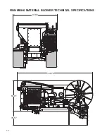
Page 84: ...78 FINN MBH6 MATERIAL BLOWER TECHNICAL SPECIFICATIONS 166 78 31 57 67 91 97 86 ...
Page 86: ...80 NOTES 80 ...
Page 106: ...MBH6 MR1108 Rev A 100 WHEN ORDERING PARTS BE SURE TO STATE SERIAL NUMBER OF MACHINE 4 2 5 1 3 ...


