57
CONTROL PANEL GUIDE AND SYSTEM OPERATION (CONTINUED)
OPTIONS SCREEN - REGENERATION (CONTINUED)
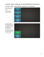
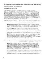
STATIONARY REGENERATION BY ENGINE MANAGEMENT
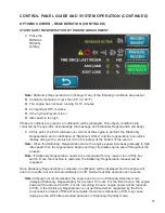
4. Press the
MANUAL
REGEN
softkey.
Note:
Stationary Regeneration will not begin if any of the following conditions are present:
Coolant temperature is less than 60° C (140° F)
The engine has not been running for 15 minutes
An important DTC is active
If the hydraulic system is on
Idle speed is too high
If these conditions are present, a notification will be displayed. Once these conditions are
corrected by the operator, acknowledge the message and Stationary Regeneration will begin.
5. At this point, the ECU will take over control of the engine to perform the Stationary
Regeneration and a notification of “Stationary Active” and the regeneration icon will be
display along with a status bar (0 to 35 minutes) at the bottom of the screen.
Note:
When the Stationary Regeneration starts, the engine speed increases gradually to high
idle speed, then the regeneration begins and may modulate engine speed throughout the
process.
Note:
If Stationary Regeneration needs to be interrupted for any reason, turn off the key
switch. Once the machine is restarted, the Stationary Regeneration request will be
repeated.
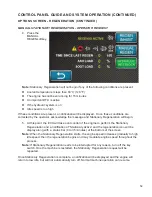
Once Stationary Regeneration is complete, a notification will be displayed and the engine will
return to low idle, but will not automatically turn off. Normal machine operation can resume.
Note:
Although not recommended, the engine can be run in Stationary Standby mode
(delaying Stationary Regeneration) for a total of 10 hours. For the first 2 hours, the engine
power will be reduced to 85%. For the remaining 8 hours, engine power will be reduced
to 50%. If the Stationary Regeneration is not performed when requested by the ECU,
an excessive amount of PM will accumulate. Abnormal combustion of PM may cause
damage to the DPF after extended operation in Stationary Standby mode.
Summary of Contents for A2548-001
Page 4: ......
Page 75: ...69 THIS PAGE LEFT BLANK INTENTIONALLY ...
Page 82: ...76 Lubrication Chart Top View of Unit 1 3 2 9 1 12 16 14 6 17 10 8 15 5 7 4 11 1 1 13 5 3 4 ...
Page 84: ...78 FINN MBH6 MATERIAL BLOWER TECHNICAL SPECIFICATIONS 166 78 31 57 67 91 97 86 ...
Page 86: ...80 NOTES 80 ...
Page 106: ...MBH6 MR1108 Rev A 100 WHEN ORDERING PARTS BE SURE TO STATE SERIAL NUMBER OF MACHINE 4 2 5 1 3 ...

