


Page 12
Translation of the original instructions with assembly instructions AF 172 G2, Filtration Group GmbH, 09.12.17, Mat. No. 70355433, Version 05
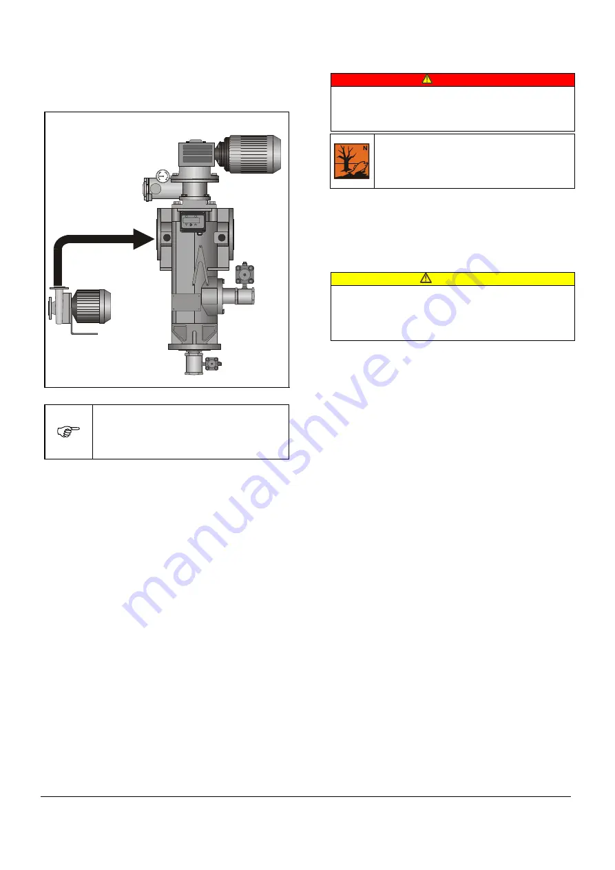
Initial differential pressure
The initial differential pressure varies according to the
application.
General guide:
Installation on discharge side: delta p
≤
0.1 bar
1
2
bar
kPa
psi
Fig. 11:
Initial differential pressure
After a cleaning cycle, the differential
pressure must return almost to the original
initial differential pressure.
If it does not, the cleaning function is faulty (in
this case, please consult the manufacturer).
11
Normal operation
DANGER!
Danger due to high pressure in the automatic filter!
Risk of injury to persons or damage to property
•
Do not allow concentrate to spatter into the
atmosphere!
Always dispose of concentrate in a manner
which does not pollute the environment!
Consult the responsible authorities before
deciding upon the most suitable disposal
method.
The following must be monitored daily during normal
operation:
•
Differential pressure
•
Controller functions
To rinse the drain line
CAUTION!
A high proportion of fine dirt particles in a long pipe
can lead to clogging!
Risk of injury to persons or damage to property
•
Rinse the drain line daily / weekly, depending on the
application.
•
Open the drain valve manually for approx. 10 - 15 s.
The drain line is rinsed
.
12
Shutting down the automatic filter
12.1 Temporary shut-down
On the installed automatic filter controller:
•
Switch OFF the main switch.
12.2 Prolonged shut-down (> 48 h)
•
Start a cleaning process manually.
•
Remove the filter insert (section 15.6).
•
Clean the filter insert (section 15.8.1).
•
Reinstall the filter insert.
•
Fill the automatic filter completely with liquid.
•
Switch OFF the main switch.
12.3 Emergency shut-down
•
Switch OFF the main switch.
The power supply is interrupted.
13
Notes on cooling lubricant filtration
•
Do not attempt to filter magnetic chips. Exercise caution
when grinding grey cast iron or steel.
•
Install a suitable preseparator (800 - 1000 µm).
•
Treat the cooling lubricant carefully. Take steps to
prevent excessive bacterial or fungal attack.
•
Cooling lubricant that has been used for the cleaning
process must be treated separately. There is a risk of
enrichment with fine dirt if it is returned to the cooling
lubricant cycle.
•
Provide a constant-pressure valve in the drain line if the
pressure on the filtered fluid side varies between 4 and
16 bar. The rinsing effect is impaired if the pressure
difference is too high during the cleaning process.
Filter discharge
side


