background image

Expanded Enclosures

Installation Guide

Manual P/N: 06-185

Revision No:  1, 11/01

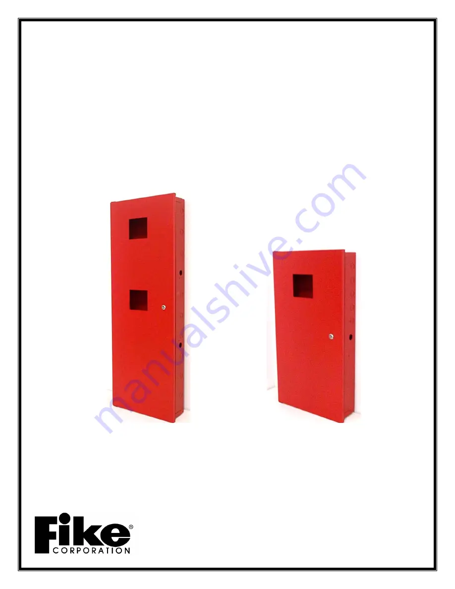
THREE BAY

EXPANDED ENCLOSURE

10-055-3-C  CHEETAH / SHP
10-060-3-C                 SHARK

TWO BAY

EXPANDED ENCLOSURE

10-055-2-C   CHEETAH / SHP
10-060-2-C                  SHARK

Summary of Contents for 10-055-2-C

Page 1: ...ded Enclosures Installation Guide Manual P N 06 185 Revision No 1 11 01 THREE BAY EXPANDED ENCLOSURE 10 055 3 C CHEETAH SHP 10 060 3 C SHARK TWO BAY EXPANDED ENCLOSURE 10 055 2 C CHEETAH SHP 10 060 2 C SHARK ...

Page 2: ......

Page 3: ...f Fike Corporation Warranties Fike provides a one year limited manufacturer s warranty on this product The standard warranty is printed in each Marketing Price List All warranty returns must be returned from an authorized Fike Sales outlet Contact Fike s Marketing Department for further warranty information Fike maintains a repair department that is available to repair and return existing electron...

Page 4: ......

Page 5: ...rovals 3 2 3 Agency Standards and Compliance 3 4 2 4 Related Documentation 4 2 5 Expanded Enclosure Features 4 3 0 EQUIPMENT PRODUCTS 5 3 1 Equipment Products 5 7 3 2 Equipment Products Spare Parts 8 3 3 Enclosure Specifications 9 14 4 0 DESIGN 15 4 1 Identify Local Code Requirements 15 4 2 Identify Specification and End User Customer Requirements 15 4 3 Ensure Proper Mounting Location 15 5 0 INST...

Page 6: ......

Page 7: ...alled the system you can contact Fike Product Support at 816 229 3405 Monday through Friday 8 00 a m to 5 00 p m CST 1 3 REVISION HISTORY Document Title Fike Expanded Enclosure Installation Guide Document Reorder Number 06 185 Revision Section Date Reason for Change 0 All Sections 02 01 Initial Release 1 All Sections 09 01 Added Shark Information 1 4 TERMS USED IN THIS MANUAL The following termino...

Page 8: ...stems This manual refers to only the mounting hardware but electronics are frequently shipped with the mounting hardware Each electonic control board contains static sensitive components Handle the module by the edges only and avoid touching the integrated components Keep the module in the protective static bags it was shipped in until time for installation Always ground yourself with a proper wri...

Page 9: ...ries S2203 Factory Mutual FM 3009544 California State Fire Marshall CSFM Planned City of New York MEA Red Enclosures Only 0101057 2 3 AGENCY STANDARDS AND COMPLIANCE This Fire Alarm Control Panel complies with the following NFPA standards NFPA 1 Fire Prevention Code NFPA 13 Sprinkler Systems NFPA 25 Water Based Fire Protection Systems NFPA 70 National Electrical Code Article 300 Wiring Methods NFP...

Page 10: ...ocument Title Part Number Cheetah Manual 06 148 Shark Manual 06 180 SHP Manual 06 130 VESDA LaserCompact Installation Guide 06 189 2 5 EXPANDED ENCLOSURE FEATURES Optional door unused opening cover plate secured by metal hardware Cheetah SHP only Optional Mounting Plate for a pair of batteries up to 18 Amp Hour used to keep batteries off enclosure and allow use of the bottom knock outs Enclosure b...

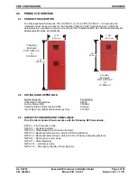
Page 11: ...ounting plates in the bottom bay the panel will be shipped with vinyl caps covering the bottom bay press studs Electrical knockouts are located on all sides for wire entry 3 0 EQUIPMENT PRODUCTS 3 1 EQUIPMENT PRODUCTS The 10 055 10 060 Expanded Enclosures consists of a red or gray metal enclosure with removable door The enclosures may be flush or surface mounted They include a 0 5 1 27 cm lip arou...

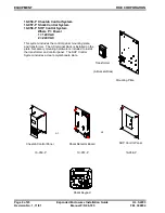
Page 12: ...20 VAC 2 240 VAC This system includes the control panel mounting plate and transformer The AC terminal block is installed on the plate Necessary mounting hardware is included to install the transformer and control panel The SHP Control System includes a clear polycarbonate plate SYSTEM FIRE ALARM Shark Keypad Transformer Mounting Plate Cheetah Control Panel 10 059 P SHP Control Panel 10 058 P Shar...

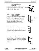
Page 13: ...middle or bottom bay of the three bay enclosure Holes are provided on the enclosure to facilitate exhaust requirements for the Compact unit Use the supplied grommets to cover the edges of the exhaust holes It is approximately 12 30 5 cm wide by 11 27 94 cm high 10 2347 Optional Mounting Plate 4 Square Addressable Modules This kit provides a stainless steel mounting plate and necessary mounting har...

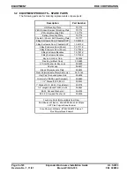
Page 14: ...oor Shark 70 1771 C 3 Bay Enclosure Door Shark 70 1765 C 2 Bay Enclosure Backbox 70 1767 C 3 Bay Enclosure Backbox 70 1769 C Key and Lock w Cam 02 1606 Fike Key without Cam 02 4983 Star Washer for Key Lock 02 3828 Shark Logo 02 4837 Black Polycarbonate Plate 02 4832 Clear Polycarbonate Plate SHP only 02 10145 Vinyl Cap for unused press stud 02 4836 Grommet VESDA LaserCompact 02 4883 1 1 2 Standoff...

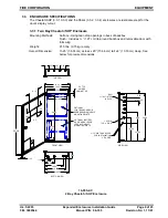
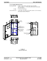
Page 15: ...door with full swing Weight 21 5 lbs 9 75 kg empty Over all Dimension 15 25 38 74 cm across x 29 73 66 cm tall x 4 10 16 cm deep See below for precise dimensions 4 00 5 51 11 16 1 75 BOTTOM VIEW 12 60 14 35 10 86 11 00 26 20 29 00 10 00 TYP FRONT VIEW 4 5 4 00 3 6 6 19 15 25 12 56 14 25 TOP VIEW 2 25 3 25 3 37 3 25 EKO 1 1 8 x 7 8 TYP 16 PLCS SIDE VIEW OPTIONAL BATTERY ADDR MODULES OR VESDA COMPAC...

Page 16: ...n 15 25 38 74 cm across x 29 73 66 cm tall x 4 10 16 cm deep See below for precise dimensions 4 00 5 51 11 16 1 75 BOTTOM VIEW 12 60 14 35 10 86 11 00 26 20 29 00 10 00 TYP FRONT VIEW 3 6 6 19 15 25 12 56 14 25 TOP VIEW 2 25 3 25 3 37 3 25 EKO 1 1 8 x 7 8 TYP 16 PLCS SIDE VIEW OPTIONAL BATTERY ADDR MODULES OR VESDA COMPACT MOUNTING PLATE 3 16 DIA THRU HOLES FOR INSTALLATION 2 EA SIDE OPTIONAL CONT...

Page 17: ...nsion 15 25 38 74 cm across x 43 109 22 cm tall x 4 10 16 cm deep See below for precise dimensions OPTIONAL CONTROL BOARD OR ADDRESSABLE MODULE MOUNTING PLATE 40 20 3 16 DIA THRU HOLES FOR INSTALLATION 2 EA SIDE 11 16 14 35 BOTTOM 1 75 10 86 12 60 5 51 4 00 43 00 FRONT 10 00 TYP 4 5 OPTIONAL BATTERY ADDR MODULES OR VESDA COMPACT MOUNTING PLATE 15 00 SIDE 14 00 12 00 1 25 DIA TYP 6 PLCS 14 00 42 00...

Page 18: ...Dimension 15 25 38 75 cm across x 43 109 22 cm tall x 4 10 16 cm deep See below for precise dimensions 10 060 3 C 3 Bay Shark Enclosure OPTIONAL CONTROL BOARD OR ADDRESSABLE MODULE MOUNTING PLATE 50 TYP 4 SIDES CABINET LIP 5 51 1 75 4 00 12 60 14 35 10 86 43 00 11 00 15 25 14 25 12 56 2 25 3 37 3 25 3 25 42 00 3 16 DIA THRU HOLES FOR INSTALLATION 2 EA SIDE 1 25 DIA TYP 6 PLCS 14 00 15 00 14 00 12 ...

Page 19: ...r mounting plate installation Plate Assembly for Cheetah Shark SHP Control Panel 10 059 1 2 Cheetah 10 060 1 2 Shark 10 058 1 2 SHP 1 Stainless Steel Plate with terminal strip installed 2 Transformer 3 Control Panel 4 Nut and Washer Kit Weight 2 Lbs 907 18 grams plus Transformer Plate Assembly High Level Interface Board P N 10 2345 1 Stainless Steel Plate 2 Nut and Washer Kit 3 Screw and Washer Ki...

Page 20: ...mbly Addressable Modules P N 10 2347 One plate will support six modules 1 Stainless Steel Plate 2 12 Standoffs M F 6 32 x 1 5 3 12 Standoffs F F 6 32 x 1 4 12 Hinge Standoffs M M 6 32 x 5 5 Nut and Washer Kit Weight 2 Lbs Plate Assembly for Batteries P N 10 2348 1 Stainless Steel Plate 2 Nut and Washer Kit Weight 2 Lbs TYP 3 38 1 75 10 00 13 50 3 25 TYP TYP 1 00 3 38 1 19 TYP 11 00 12 00 TYP 0 50 ...

Page 21: ...tection system while it is still in the design stage versus when the project has started and you are under a deadline to complete the project 4 2 IDENTIFY SPECIFICATION AND END USER CUSTOMER REQUIREMENTS Identify the needs of the customer and ensure that they meet the requirements of 4 1 above and 4 3 below The customer is the final user of the system and needs to be comfortable with the location ...

Page 22: ......

Page 23: ... utilize the four tear drop openings in the back of the box For flush mounting cut the opening in the wall to fit the backbox refer to Section 3 3 for dimensions Secure the box to the wall by again utilizing the four tear drops in the back of the enclosure Reference Section 3 Equipment Products for detailed specifications Determine the maximum number of conductors needed from the design Wire is to...

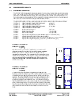
Page 24: ...ion Mounting Plates are to be inserted over the press studs extending out from the backbox and secured with lock washers and hex nuts Connect all hardware to the backbox and mounting plate s as described to prepare for installing electronic assemblies Optional Battery Mounting Plate Optional Cheetah Shark SHP Mounting Plate Optional VESDA HLI Mounting Plate Optional VESDA LaserCompact Mounting Pla...

Page 25: ... on the control panel ordered the appropriate labeling kit will be shipped Cheetah SHP enclosure will have the Fike logo silk screened on the door Shark enclosure will come with a Shark label Install the Shark Control Panel label on the lower right corner of the enclosure front door Apply other labeling inside front door Write sales outlet name address and phone number on System Service label Door...

Page 26: ... door Detail C Shark only 5 Wire transformer and Shark keypad if necessary as described in the appropriate manual 5 4 INSTALL INTERNAL ELECTRONIC ASSEMBLIES Wear grounding strap while installing internal electronic assemblies Reference the appropriate control panel manual for proper installation procedure of control equipment 5 4 1 Control Systems Mounting Plate 6 32 Hex Nut w Washer Typ 8 Plcs Ba...

Page 27: ...l P N 06 185 Revision No 1 11 01 Shark Detector Assembly Shark Control Board Mounting Plate 6 32 Hex Nut w Washer Typ 8 Plcs Hex Nut w Star Washer 4 Plcs Keypad Cable ass y p n 02 4810 Mounting Plate Shark Control Board Enclosure with door p n 02 4992 Ground Strap 10 AWG Detail B Detail C Shark Keypad Assembly ...

Page 28: ...m bay of the 2 bay enclosure and the middle or bottom bay of the 3 bay enclosure Determine the direction of the VESDA Compact unit sold separately before installing the mounting plate can be mounted up or down Mount with side tabs facing up or down to support direction of compact Attach to enclosures with hex nu and washers as shown Grommet should be inserted in hole provided on enclosure t suppor...

Page 29: ...ashers provided When attaching modules sold separately use 1 standoffs on one side of module and the 1 standoff with the hinged standoff on the other side as shown Module hardware is provided with plate assembly Note Module covers will not fit when using all locations BATTERY BATTERY Mounting plate 6 32 Screw w Washer Typ 4 Plcs Back inside of Enclosure 1 Standoff F F Qty 12 Mounting Plate 1 Stand...

Page 30: ...704 South 10 th Street P O Box 610 Blue Springs Missouri 64013 U S A 816 229 3405 Fax 816 229 5082 http www fike com ...

Reviews: