A. Technical appendix
A−7
Festo P.BE−VIFB11−03−EN en 0503g
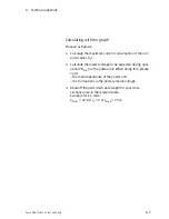
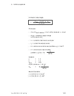
Calculating with the graph
Proceed as follows:
1. Calculate the maximum current consumption of the out
puts/valves (I
2
).
2. Calculate the lowest voltage to be expected during oper
ation (VB
min
) on the power unit. When doing this, please
note:
the load dependency of the power unit
the fluctuations in the primary mains voltage
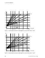
3. Read off the permitted cable length for your cross−
sectional area in the relevant table.
Example for 1.5 mm
2
:
V
Bmin
= 22.8 V, I
2
= 2 A; L
max
= 25 m
Summary of Contents for IFB11-03
Page 2: ......
Page 4: ...Contents and general instructions II Festo P BE VIFB11 03 EN en 0503g...
Page 18: ...Contents and general instructions XVI Festo P BE VIFB11 03 EN en 0503g...
Page 19: ...Summary of components 1 1 Festo P BE VIFB11 03 EN en 0503g Chapter 1...
Page 28: ...1 Summary of components 1 10 Festo P BE VIFB11 03 EN en 0503g...
Page 29: ...Fitting 2 1 Festo P BE VIFB11 03 EN en 0503g Chapter 2...
Page 39: ...Installation 3 1 Festo P BE VIFB11 03 EN en 0503g Chapter 3...
Page 71: ...Commissioning 4 1 Festo P BE VIFB11 03 EN en 0503g Chapter 4...
Page 89: ...4 Commissioning 4 19 Festo P BE VIFB11 03 EN en 0503g Fig 4 4 I O configuration DLC 100...
Page 122: ...4 Commissioning 4 52 Festo P BE VIFB11 03 EN en 0503g...
Page 123: ...Diagnosis and error treatment 5 1 Festo P BE VIFB11 03 EN en 0503g Chapter 5...
Page 144: ...5 Diagnosis and error treatment 5 22 Festo P BE VIFB11 03 EN en 0503g...
Page 145: ...Technical appendix A 1 Festo P BE VIFB11 03 EN en 0503g Appendix A...
Page 159: ...Accessories B 1 Festo P BE VIFB11 03 EN en 0503g Appendix B...
Page 206: ...B Accessories B 48 Festo P BE VIFB11 03 EN en 0503g...
Page 207: ...Index C 1 Festo P BE VIFB11 03 EN en 0503g Appendix C...
Page 208: ...C Index C 2 Festo P BE VIFB11 03 EN en 0503g C Index C 1...
Page 214: ...C Index C 8 Festo P BE VIFB11 03 EN en 0503g...


