background image

4

Product overview

4.1

Scope of delivery

Component

Number

Servo drive CMMT-AS-...

1

Operating instructions CMMT-AS-...

1

Tab. 6: Scope of delivery

4.2

System structure

The servo drive CMMT-AS is a 1-axis servo drive. Depending on the product
variant, the following components, which are necessary for standard applications,
are integrated into the device or into the cooling profile of the device:

Mains filter (guarantees immunity to interference and limits conducted emis-
sions)

Electronics for DC link voltage conditioning

Power stage (for motor control)

Braking resistor (integrated into the cooling element)

Brake chopper (switches the braking resistor in the DC link circuit, if and when
required)

Temperature sensors (for monitoring the temperature of the power module and
of the air in the device)

Fan in the cooling profile (depending on product variant)

The servo drive features a real-time Ethernet interface for process control. Var-
ious bus protocols are supported depending on the product design (EtherCAT,
EtherNet/IP or PROFINET).
The device can be parameterised via a PC using either the real-time Ethernet
interface or the separate standard Ethernet interface.

Festo recommends use of servo motors, electromechanical drives, lines and
accessories from the Festo accessory programme.

1

2

3

4

5

6

7

8

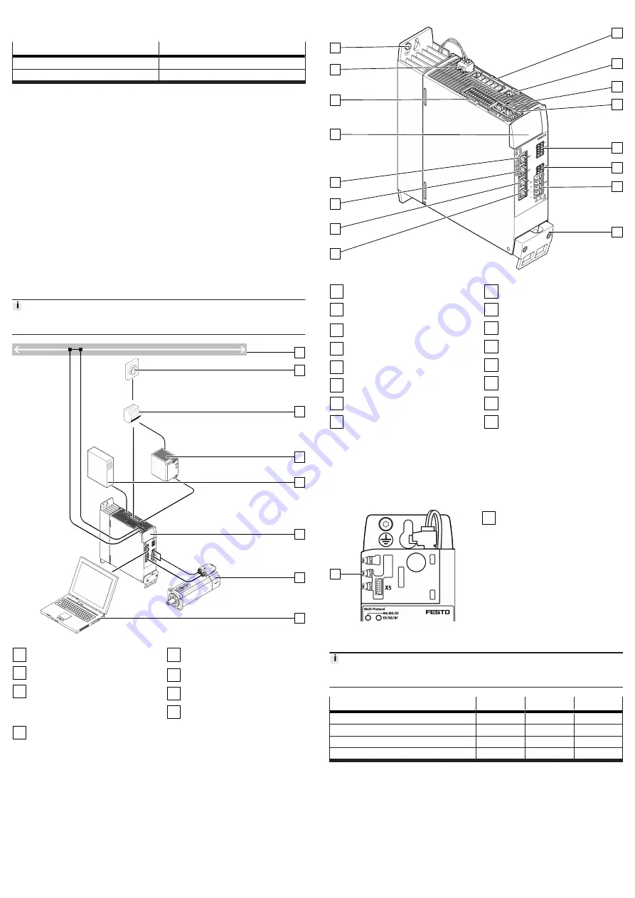
Fig. 1: System structure (example)

1

Bus/network

2

Main switch

3

Automatic circuit breaker/fuses
and all-current-sensitive RCD
(residual current device)
(optional)

4

Fixed power supply for logic
voltage supply 24 V DC (PELV)

5

External braking resistor
(optional)

6

Servo drive CMMT-AS

7

Servo motor (here EMME-AS)

8

PC with Ethernet connection for
parameterisation

4.2.1

Overview of connection technology

1

2

3

4

5

6

7

8

9

10

11

12

13

14

15

16

Fig. 2: Connections of the CMMT-AS-C2-11A-P3 (example)

1

PE connection, housing

2

[X9A] Mains and DC link circuit
connection

3

[X9C] Logic voltage

4

[XF2 OUT] RTE interface port 2

5

[XF1 IN] RTE interface port 1

6

[X1C] inputs/outputs for the axis

7

[X6B] motor auxiliary connection

8

[X6A] motor phase connection

9

Shield clamp of motor cable

10

[X2] encoder connection 1

11

[X3] encoder connection 2

12

[X10] device synchronisation

13

[X18] standard Ethernet

14

[X5] connection for operator unit
(behind the blind plate)

15

[X1A] I/O interface

16

[X9B] connection for braking
resistor

4.3

Set bus protocol

The CMMT-AS-...-MP product variant supports several bus protocols.
The following options are available for setting the protocol:

automatic detection by the CMMT-AS-...-MP

Configuration in the CMMT-AS plug-in

direct specification via SW1 to SW3

1

Fig. 3: Switches SW1, SW2, SW3 with

the CMMT-AS-...-MP

1

Switches SW1, SW2, SW3

Protocols supported by the firmware version used 

è

 Manual/online help plug-in,

software, function, fieldbus, device profile.

Protocol

Size 3

Size 2

Size 1

Auto (detection or parameterisation)

0

0

0

PROFINET

0

0

1

EtherCAT

0

1

0

EtherNet/IP

0

1

1

Tab. 7: Switch setting bus protocol
The switches can be adjusted with a small slotted head screwdriver.
The switch position is evaluated once when the device is started.
4.4

Safety sub-functions

4.4.1

Function and application

The servo drive CMMT-AS-...-S1 has the following safety-related performance fea-
tures:

Safe torque off (STO)

Safe brake control (SBC)

Summary of Contents for CMMT-AS-C2-11A-P3 S1 Series

Page 1: ...nd the necessary external circuit breaker Data matrix code 123456789AB Product key as a data matrix code and an 11 character alphanumeric code Festo SE Co KG Manufacturer DE 73734 Esslingen Manufacturer s address Made in Germany Country of origin Germany 1 only for product versions with corresponding restrictions Tab 2 Product labelling example Warning symbols on the front of the product Warnin g ...

Page 2: ...tor The safety sub function SBC is intended to safely hold the motor and axis in position at standstill The safety sub function SS1 is intended for performing a rapid stop with subse quent torque switch off 2 2 1 Application areas The device is intended for use in an industrial environment and with appropriate measures in commercial residential and mixed areas The device is intended for installati...

Page 3: ...DC PELV 5 External braking resistor optional 6 Servo drive CMMT AS 7 Servo motor here EMME AS 8 PC with Ethernet connection for parameterisation 4 2 1 Overview of connection technology 1 2 3 4 5 6 7 8 9 10 11 12 13 14 15 16 Fig 2 Connections of the CMMT AS C2 11A P3 example 1 PE connection housing 2 X9A Mains and DC link circuit connection 3 X9C Logic voltage 4 XF2 OUT RTE interface port 2 5 XF1 I...

Page 4: ...r holding brakes or clamping units which engage in the de energised state Ensure the lines are protected when installed SBC request The safety sub function SBC is requested on 2 channels by simultaneously switching off the control voltage at both control inputs SBC A and SBC B The SBC A request switches off the power to the signals BR BR The SBC B request switches off the power to the signal BR EX...

Page 5: ...for cross wiring For DC link coupling higher power devices must be placed closer to the mains supply If there is a voltage supply to the device when the control cabinet is open vertical access to the bottom and top of the device must be prevented For mounting on the rear wall of the control cabinet the servo drive cooling element has a slot on the top in the shape of a keyhole and an ordinary slot...

Page 6: ... a DC current of 10 mA Always connect both protective earthing connections to the mains side PE connection the PE pin of X9A and PE earthing screw on the housing The minimum cross section of the protective earthing conductor must comply with the local safety regulations for protective earthing conductors for equipment with high leakage current 7 3 Mains fuse The CMMT AS does not have an integrated...

Page 7: ...ernal mains filter Accessories Tab 16 Installation measures to achieve the specified category To install a line choke è 7 7 Connection examples If set up and commissioning are performed by a professional with the neces sary experience for setting up and commissioning drive systems including their EMC aspects category C2 devices can be used in the first environment residential area For operation of...

Page 8: ...Control input Safe torque off channel B 10 SBC A Control input Safe brake control channel A X1A Pin Function Description 9 SBC B Control input Safe brake control channel B 8 reserved do not connect 7 6 5 4 ERR RST Error acknowledgement 3 CTRL EN Power stage enable 2 AIN0 Differential analogue input 1 AIN0 Tab 17 Inputs and outputs for the higher order PLC with the CMMT AS S1 Requirements for the c...

Page 9: ...der emulation Incremental encoder input Input of a slave axis for receiving the encoder signals of a master axis Tab 24 Possible functions of the connection X10 Requirements for the connecting cable Characteristics Encoder cable for servo drives shielded Optical shield cover 85 Separately twisted signal pairs recommended design 4 x 2 x 0 25 mm2 Max cable length 3 m Tab 25 Requirements for the conn...

Page 10: ...e potential 2 BR Holding brake positive potential 1 FE Functional earth con nected to protective earth Tab 34 Motor auxiliary connection Requirements for the connecting cable Design 2 wires for the line to the holding brake twisted in pairs separately shielded 2 wires for the line to the temperature sensor twisted in pairs separately shielded Min conductor cross section including wire end sleeve w...

Page 11: ...th larger cable diameter 11 mm 15 mm 0 5 Nm 15 With a higher tightening torque make sure the con necting cable does not get crushed in the clamping area due to excessive pressure Tab 37 Tightening torque and clamping range CMMT AS C2 C3 C5 11A P3 1 2 3 4 5 Fig 11 Shield clamp of the motor cable 1 Retaining screws of the shield clamp 2 Motor cable 3 Cut out for mounting cable binders 2x 4 Shield cl...

Page 12: ...resistors Information on selecting suitable braking resistors è Manual Assembly Installa tion 7 11 Cross wiring Cross wiring makes it possible to set up a device compound consisting of up to 10 servo drives CMMT AS The different cross wiring options are as follows Cross wiring of I O signals at the connection X1A Cross wiring of the mains and logic voltage supply without DC link coupling Cross wir...

Page 13: ...d to connected components becoming overloaded or damaged Do not enable the closed loop controller until the configured components servo drive motor axis etc match those that are connected exactly During initial commissioning with the Festo Automation Suite with the CMMT AS plug in installed the following steps must be performed for example 1 Perform configuration and parameterisation with the CMMT...

Page 14: ...he system against accidental reactivation 3 Wait at least 5 minutes until the intermediate circuit has discharged 4 Let the device cool down to room temperature 5 Before touching the power connections X6A X9A X9B check to ensure they are free of voltage 6 Disconnect all electrical cables To dismount the device Loosen retaining screws 2x and remove the device from the mounting sur face 13 Technical...

Page 15: ...ge Storage temperature C 25 55 Relative humidity 5 95 non condensing Permissible altitude m 3000 above sea level Tab 58 Ambient conditions storage Ambient conditions operation Ambient temperature at nom inal power C 0 40 Ambient temperature with derating 3 C at 40 C 50 C C 0 50 Cooling via ambient air in the control cabinet from CMMT AS C5 11A P3 also via forced ventilation through an inte grated ...

Page 16: ...ns of Underwriters Laboratories Inc UL for USA and Canada UL CSA certification information Product category code NMMS NMMS7 Power Conversion Equipment File number E331130_Vol 1_Sec 3 Considered standards UL61800 5 1 Adjustable Speed Electrical Power Drive Sys tems CSA C22 2 No 274 17 Adjustable Speed Drive UL mark UL control number 4PU8 Tab 65 UL CSA certification information Use in an environment...

Reviews: