


WARNING
Risk of injury from electric shock in the event of incomplete insulation at the
power connections [X6A], [X9A] and [X9B].
Before operating, plugging in or unplugging the operator unit CDSB or a con-
nector from a hot-plug-capable interface, the following points must be fulfilled:
• The conducting lines at the device are completely insulated.
• The protective earthing (PE) and the shield connection are correctly connected
to the device.
• The housing is free of damage.
WARNING
Risk of injury due to overheating and electric shock with faulty live components
Closing the branch-circuit protective device with faulty live components may
cause fire or electric shock.
• The opening of the branch-circuit protective device may be an indication that a
fault current has been interrupted. To reduce the risk of fire or electric shock,
current-carrying parts and other components of the controller should be exam-
ined and replaced if damaged. If burnout of the current element of an overload
relay occurs, the complete overload relay must be replaced.
Information for operation with safety functions
NOTICE
Check the safety functions to conclude the installation process and after every
modification to the installation.
During installation of safety-related inputs and outputs, also observe the fol-
lowing:
–
Comply with all specified requirements, e.g.:
–
Surrounding area (EMC)
–
Logic and load voltage supply
–
Mating plug
–
Connecting cables
–
Cross-wiring
–
Additional information
è
Manual Assembly, Installation.
–
The maximum permissible cable length between the safety relay unit and the
plug of the I/O interface is 3 m.
–
Comply with the requirements of EN 60204-1 for the installation. In the event of
a fault, the voltage must not exceed 60 V DC. The safety relay unit must switch
off its outputs in the event of a fault.
–
Install wiring between the safety relay unit and the I/O interface of the servo
drive in such a way as to eliminate the risk of a short circuit between the
conductors or to 24 V, as well as a cross circuit
è
EN 61800-5-2, Annex
D.3.1. Otherwise, the safety relay unit must feature detection of shorts across
contacts and, in the event of a fault, must switch off the control signals on 2
channels.
–
Use only suitable mating plugs and connecting cables
è
Manual Assembly,
Installation.
–
Prevent conductive contamination between neighbouring plug pins.
–
Make sure that no bridges or similar can be inserted parallel to the safety
wiring. For example, use the maximum wire cross section or appropriate plastic
wire end sleeves.
–
Use twin wire end sleeves for cross-wiring safety-related inputs and outputs.
A maximum of 10 devices may be cross-wired when cross-wiring inputs and
outputs
è
Manual Assembly, Installation.
–
The safety relay unit and its inputs and outputs must meet the necessary safety
classification of the safety function that is required for the specific case.
–
Connect each of the control inputs to the safety relay unit on 2 channels using
parallel wiring.
–
Only use permitted motor cables for the BR+/BR– connection.
–
If the diagnostic output of the safety sub-function concerned has to be evalu-
ated: connect diagnostic output directly to the safety relay unit. Evaluation
of the diagnostic output is either mandatory or optional depending on which
safety classification is desired.
–
If diagnostic outputs are cross-wired for a device compound: wire diagnostic
outputs as a ring. Run the two ends of the ring to the safety relay unit and
monitor for discrepancies.
7.2
Residual current protective device
WARNING
Risk of injury from electric shock.
This product can cause a DC current in the residual-current conductor in case of
error. In cases where a residual current device (RCD) or a residual current monitor
(RCM) is used to protect against direct or indirect contact, only the type B kind of
RCD or RCM is permitted on the power supply side of this product.
Information on the residual current protective device
è
Manual Assembly, Instal-
lation.
The touch current in the protective earthing conductor can exceed an alternating
current of 3.5 mA or a DC current of 10 mA. Always connect both protective
earthing connections to the mains-side PE connection, the PE pin of [X9A] and
PE earthing screw on the housing. The minimum cross section of the protective
earthing conductor must comply with the local safety regulations for protective
earthing conductors for equipment with high leakage current.
7.3
Mains fuse
The CMMT-AS does not have an integrated fuse at the mains input or in the DC
link circuit. An external fuse is required at the mains supply of the device. A device
group coupled in the DC link circuit must be protected by a common mains fuse.
•
Use only circuit breakers and fuses that have the relevant approval and meet
the specifications and protection requirements stated below.
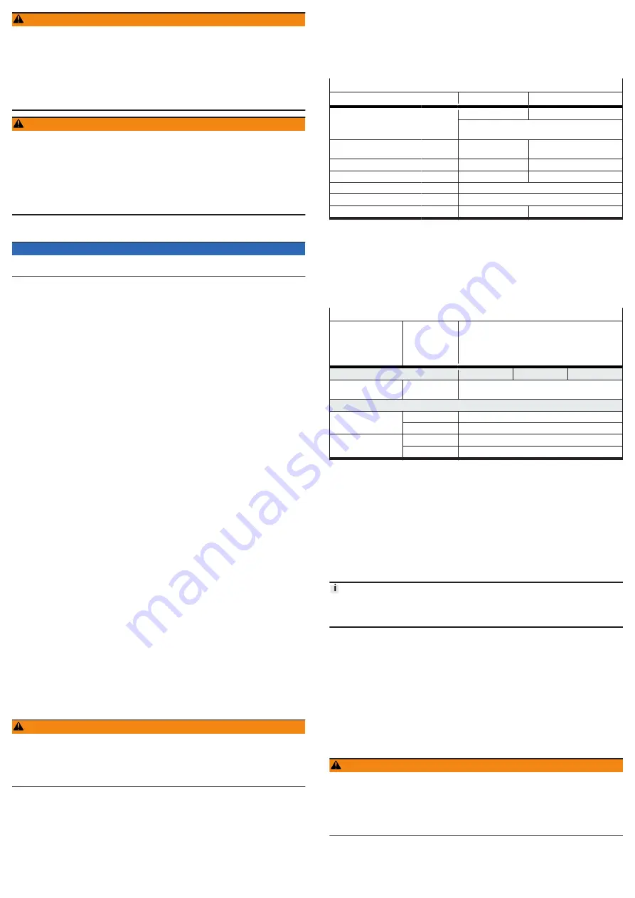
Requirements for circuit breakers (automatic circuit breakers) and fuses
Type of protection
Circuit breaker
Class J fuse
max. permissible rated cur-
rent
[A]
40
25
Restrictions concerning line protection
Short circuit current rating
SCCR of mains fuse
[kA]
min. 10
min. 100
Approvals
IEC 60947-2
CE certification
Rated voltage
[V AC]
min. 400
600
Overvoltage category
III
Pollution degree
2
Characteristic
C
slow-blowing
Tab. 13: Requirements for circuit breakers and fuses
In the case of electricity networks with a SCCR > 10 kA, only class J fuses are
permitted.
The circuit breaker is used for line protection. The rated current of the circuit
breaker must be less than or equal to the approved current rating of the selected
conductor cross section. The circuit breaker must also take into account the
overload case and must not trip (overload case: a 3-fold increase in the input
current for 2 s).
Line protection requirements
Description
Cable cross
section at
[X9A] in
[mm²]
Mains fuse [A]
1)
CMMT-AS-
C2-11A-P3
C3-11A-P3
C5-11A-P3
Minimum fuse protec-
tion
1.5
6
Maximum fuse protection of an individual device or a device group
without heat-resistant
cable
4
25
6
32
with heat-resistant
cable
2)
4
32
6
40
1) Specifications according to DIN VDE 0298-4:2013, permissible currents according to EN 60204-1 may
differ (depending on installation type and temperature)
2) no derating up to an ambient temperature of 50 °C and a cable temperature higher than 70 °C (max. cable
temperature 90 °C)
Tab. 14: Line protection requirements
Fuse protection when load circuit is supplied with DC power
The CMMT-AS allows the load circuit to be supplied with DC power. With DC
power, external fuse protection is once again required in the form of short circuit
protection and line protection. The fuse that is used must be capable of reliably
disconnecting the maximum DC supply voltage that could occur and the potential
short circuit current (SCCR
DC
).
Maximum fuse protection: 40 A
If fuse protection is to be avoided on the DC side, check whether the fuse protec-
tion could alternatively be installed on the AC side upstream of the DC fixed power
supply.
7.4
Permissible and impermissible mains types of system earthing
Information on allowed and prohibited mains types of system earthing and neces-
sary measures for use in IT networks
è
Manual Assembly, Installation.
Leakage currents in IT systems
High-frequency leakage currents to protective earthing (PE) may be encountered
even in IT systems (IT = Isolé Terre) during operation of the servo drive. The
leakage currents flow to the PE through the coupling capacitances of the motor
cable and the motor and back to the servo drive through the coupling capacitance
of the isolating transformer via the load supply. The coupling capacitances can be
minimised by selection of a suitable isolating transformer and keeping the motor
cable as short as possible.
WARNING
Risk of injury from electric shock.
The servo drive generates high-frequency leakage currents, which can lead to
dangerous contact currents on the external conductors and the neutral conductor
of the IT system. Touching the mains conductor or the neutral conductor can result
in serious injuries or death.
• Before working on the IT systems, disconnect the servo drive from the mains.
7.5
Connection of the mains side PE conductor
All PE conductors must always be connected prior to commissioning for safety
reasons. Observe the regulations of EN 60204-1 when implementing protective
earthing.


