background image

44 / 52

Festo 7ELCC_TB_KFb_en

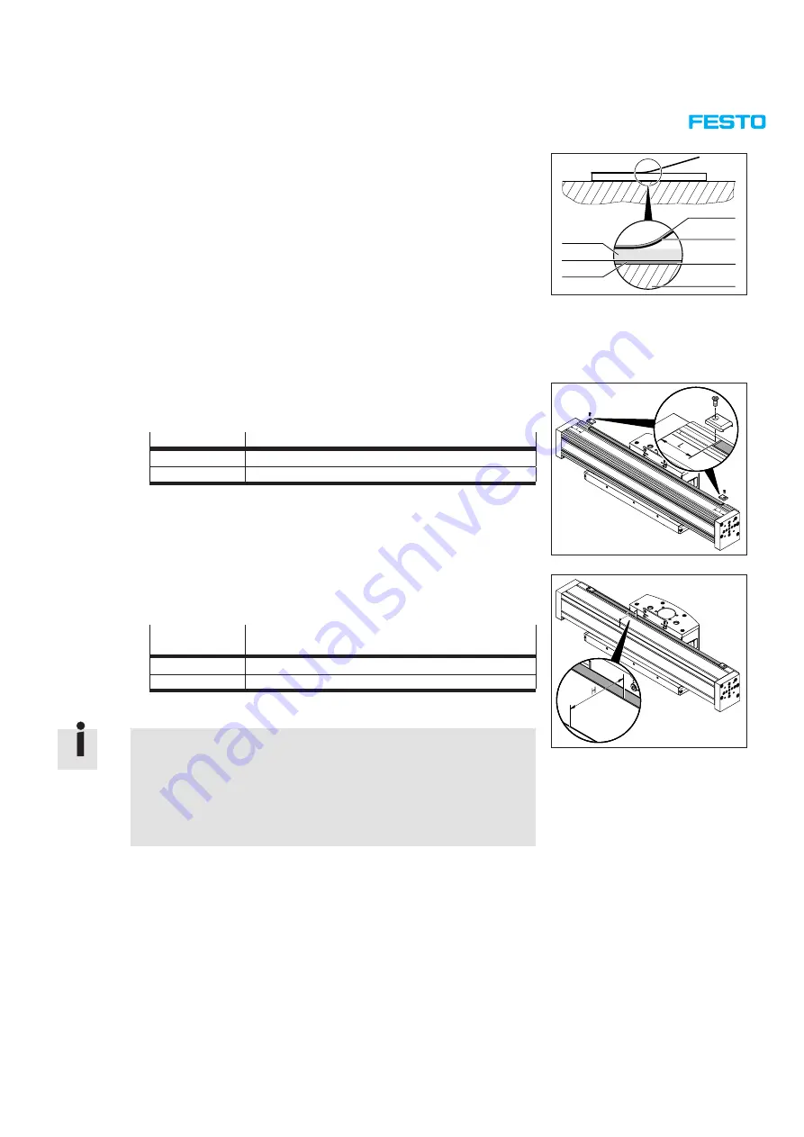
Structure of the measuring tape

1

  Cover strip

2

  Adhesive tape

3

  Adhesive tape

4

  Cylinder barrel module

5

  Steel strip

6

  Adhesive tape

7

  Magnetic strip

The magnetic strip 

7

 is already attached via an adhesive tape 

6

 to a steel 

strip 

5

 (= carrier side) in the factory.

1

4

3

2

7
6
5

7.  Stick the adhesive tape 

3

 onto the steel strip (= carrier side) 

5

.

8.  Adjust the magnetic strip with the steel strip to the middle of the cylinder 

barrel module. A size‑specific distance 

L

 from the ends of the cylinder barrel 

module must be maintained (

 Table):

Type

Distance 

L

 to the end cap

ELCC-TB-KF-60

44 mm

ELCC-TB-KF-70

49 mm

9.  Adjust the magnetic tape with the steel strip on the cylinder barrel with a 

size‑specific distance 

H

 from the front edge (= from the cylinder barrel edge 

facing away from the drive head) of the cylinder barrel module (

 Table):

Type

Distance 

H

 to the front edge of the cylinder barrel 

module

ELCC-TB-KF-60

39.5 mm

ELCC-TB-KF-70

60.5 mm

10. Stick the magnetic strip on the cylinder barrel module.

The easiest way is to stick on the magnetic strip in two steps:

1.  Remove half the protective film from the adhesive tape.
2.  Stick on the magnetic strip corresponding to the removed film.
3.  Remove the remaining length of the protective film from the adhesive 

tape.

4.  Stick on the whole length of magnetic strip.

Summary of Contents for 8060571

Page 1: ...Repair instructions en Cantilever axis ELCC TB KF 60 F1 M1 ELCC TB KF 70 F1 M1 ELCC TB KF 90 F1 ELCC TB KF 110 7ELCC_TB_KFb_en...

Page 2: ...document or communication of its contents to others without express authorisation is prohibited Offenders will be held liable for damages All rights reserved in the event that a patent utility model o...

Page 3: ...ns into consideration if necessary These repair instructions have been prepared with care Festo SE Co KG does not however accept liability for any errors in these repair instructions or their conseque...

Page 4: ...F 60 F1 bill of materials 15 3 2 ELCC TB KF 70 F1 component overview 16 3 2 1 ELCC TB KF 70 F1 bill of materials 17 3 3 ELCC TB KF 90 F1 component overview 18 3 3 1 ELCC TB KF 90 F1 bill of materials...

Page 5: ...M1 42 5 10 1 Removing the old measuring tape 43 5 10 2 Sticking on new measuring tape 43 5 10 3 Aligning the measuring unit with the measuring tape 45 5 11 Functional test and commissioning 46 5 12 S...

Page 6: ...mounting and measuring unit of the displace ment encoder on the ELCC TB KF 60 70 www festo com DAYP shock absorber retainer assembly instructions Contains information on mounting the shock absorber r...

Page 7: ...measures refer to the safety instructions on the packagings of the named materials and the current safety data sheets in accordance with Regulation EC No 1907 2006 www festo com msds Website of the p...

Page 8: ...nufacturer expire 1 6 Service Contact your regional Festo contact if you have any questions www festo com Instead of carrying out the repair yourself your local Festo sales office offers the option of...

Page 9: ...om msds website of the product manufacturer 1 9 Technical requirements Note The following instructions for safe and proper use must be observed Comply with the connection and ambient conditions of the...

Page 10: ...reversal 2x 4 Bottom belt reversal 2x 5 Roller carriage 2x 6 Blanking plate 7 Slide module 8 Cover strip 9 Toothed belt aJ Housing aA Toothed belt pulley module aB Spacing bolt 4x aC Roller module 2x...

Page 11: ...CC TB KF 110 800 0H P0 CR 8082413 ELCC TB KF 110 1000 0H P0 CR 8082414 ELCC TB KF 110 1200 0H P0 CR 8082415 ELCC TB KF 110 1500 0H P0 CR 8082416 ELCC TB KF 110 1700 0H P0 CR 8082417 ELCC TB KF 110 200...

Page 12: ...umber 3 Serial number 4 Product Key 5 Product Key Code Data Matrix Barcode http pk festo com Product Key The order code on the product labelling provides the following information ELCC Cantilever axis...

Page 13: ...pter 3 3 on page 18 Chapter 3 3 1 on page 19 8082400 8082401 8082402 8082403 8082404 8082405 8082406 8082407 8082408 ELCC TB KF 110 8082409 Chapter 3 4 on page 20 Chapter 3 4 1 on page 21 8082410 8082...

Page 14: ...14 52 Festo 7ELCC_TB_KFb_en 3 1 ELCC TB KF 60 F1 component overview...

Page 15: ...element 22 Spacing bolt 23 Toothed belt pulley module Toothed belt pulley module F1 24 Shim DIN 988 8 14 0 5 25 Roller module Roller module F1 26 End plate 27 Retaining ring DIN 472 8 0 8 28 Roller mo...

Page 16: ...16 52 Festo 7ELCC_TB_KFb_en 3 2 ELCC TB KF 70 F1 component overview...

Page 17: ...pulley module Toothed belt pulley module F1 23 Shim DIN 988 15 21 0 5 24 Roller module Roller module F1 25 End plate 26 Retaining ring DIN 472 15 1 27 Roller module Roller module F1 28 Retaining ring...

Page 18: ...18 52 Festo 7ELCC_TB_KFb_en 3 3 ELCC TB KF 90 F1 component overview...

Page 19: ...e Toothed belt pulley module F1 23 Shim DIN 988 20 28 1 24 Roller module Roller module F1 25 End plate 26 Retaining ring DIN 472 20 1 27 Roller module Roller module F1 28 Retaining ring DIN 472 75 2 5...

Page 20: ...20 52 Festo 7ELCC_TB_KFb_en 3 4 ELCC TB KF 110 components overview...

Page 21: ...Housing 20 Cushioning element 21 Spacing bolt 22 Toothed belt pulley module 23 Shim DIN 988 35 45 1 24 Roller module 25 End plate 26 Retaining ring DIN 472 35 1 5 27 Roller module 28 Retaining ring D...

Page 22: ...ometry wears very uniformly so that despite high wear the contour is maintained for a relatively long time In addition the tension members made of steel cord start to protrude out of the PU material s...

Page 23: ...s time Reliably secure the product against unauthorised restarting Note Before starting the repair work dismantle existing attachments as described in the instructions in the correspond ing operating...

Page 24: ...CC TB KF 70 CR Polychloroprene 16 mm ELCC TB KF 70 F1 Polyurethane PU1 60 mm ELCC TB KF 70 PU2 Polyurethane PU2 coated 60 mm ELCC TB KF 90 CR Polychloroprene 34 mm ELCC TB KF 90 F1 Polyurethane PU1 10...

Page 25: ...eplacing the toothed belt On replacing the toothed belt due to long operation it is useful to replace the toothed belt pulley module including deep groove ball bearings at the same time Chapter 5 2 on...

Page 26: ...4 mm 17 mm ELCC TB KF 70 4 mm 17 mm ELCC TB KF 90 5 mm 23 mm ELCC TB KF 110 6 mm 39 mm 4 Pull the toothed belt out of the clamping component modules 2x 5 Remove the housing 2 to do this push in the l...

Page 27: ...othed belt with the help of the old toothed belt 1 Use adhesive tape to attach the new toothed belt edge to edge to the old toothed belt 2 Use the old toothed belt to carefully pull the new toothed be...

Page 28: ...TB KF 60 70 the clamping plate is pressed into the clamping component module by one grub screw In the case of ELCC TB KF 90 110 the clamping plate is pressed into the clamping component module by two...

Page 29: ...ral frequency of the toothed belt is recorded using a measuring device and displayed as a frequency value in hertz Note Correct toothed belt pretension is essential for the life of the toothed belt as...

Page 30: ...Freely oscillating strand length L Pretension force FV ELCC TB KF 60 F1 0 090 kg m 150 5 mm 360 375 N ELCC TB KF 70 F1 0 150 kg m 160 5 mm 720 750 N ELCC TB KF 90 F1 0 346 kg m 168 5 mm 1440 1500 N F...

Page 31: ...80 mm 1 Feature F1 PU1 toothed belt For short strokes 99 mm Type Distance L1 ELCC TB KF 60 F1 33 mm ELCC TB KF 70 F1 33 mm ELCC TB KF 90 F1 33 mm ELCC TB KF 110 33 mm 1 Feature F1 PU1 toothed belt 2...

Page 32: ...ng the toothed belt If the measured natural frequency of the toothed belt is outside the speci fied range adjust the toothed belt pretension as follows 1 Adjust the toothed belt pretension by turning...

Page 33: ...plate secure the bottom shims 2x of the roller modules to prevent loss 7 Remove the roller modules 2x and toothed belt pulley module from the end plate 8 Secure shims 2x 9 Check the roller and toothed...

Page 34: ...bolt 4x and at the same time push the shafts of the roller modules 2x and the deep groove ball bearing of the toothed belt pulley module into the mountings of the slide module 7 Screw in socket head...

Page 35: ...m jumping off The ELCC TB KF 60 has one compression spring mounted on each top belt reversal The ELCC TB KF 70 90 110 has two compression springs mounted on each top belt reversal 2 Remove cover caps...

Page 36: ...reversals 2x from the slide module 5 4 2 Mounting the cover strip 1 Insert the bottom belt reversals 2x in the correct position in the slide module 2 Put on the cover strip The cover strip lies on the...

Page 37: ...Position the cover cap in the correct position on the compression springs 8 Push down the compression springs by pressing the cover cap 9 Push the cover cap with top belt reversal completely into the...

Page 38: ...he end cap The cover strip may not be fixed in place 25 Select the suitable clamping element depending on the axis size Table and Chapter 8 2 on page 49 Type Clamping element ELCC TB KF 60 EADT S L5 7...

Page 39: ...e been dismantled from the end cap however there may also be grub screws in the cylinder barrel 5 Remove the end cap 6 If necessary use pliers to pull out grub screws 2x each and replace 7 Dismantle t...

Page 40: ...es Chapter 5 1 1 on page 25 3 Only for cantilever axes with feature P9 Remove cover strip from the end cap Chapter 5 4 on page 34 4 Dismantle end cap Chapter 5 5 on page 39 5 Pull the clamping compone...

Page 41: ...top at the other end cap 8 Remove remaining pieces of the magnetic strips 2x do not use sharp edged tools Typical solvents for cleaning surfaces are a 50 50 isopropyl alcohol water mixture or heptane...

Page 42: ...5 Firmly press on magnetic tape with adhesive tape 6 Cut off the protective film at the slide module 7 Repeat the procedure on the other side of the cylinder barrel module 8 Push the slide module up t...

Page 43: ...as well as other contaminants The best adhesive bonding temperature lies between 21 C and 38 C Bonding is inadvisable if the surfaces to be bonded are colder than 10 C as in this case the adhesive be...

Page 44: ...Distance L to the end cap ELCC TB KF 60 44 mm ELCC TB KF 70 49 mm 9 Adjust the magnetic tape with the steel strip on the cylinder barrel with a size specific distance H from the front edge from the c...

Page 45: ...ing instruction Chapter 1 1 on page 6 www festo com 18 Comply with the tolerances for the distance and angle of the measuring unit with the measuring tape Chapter 5 10 3 on page 45 If these tolerances...

Page 46: ...to com 6 Maintenance Observe the general safety instructions Chapter 1 4 on page 7 This section contains important technical information about the maintenance work to be carried out on the product The...

Page 47: ...circulating ball bearing guide of the roller bearing Mineral based lubricant Festo LUB KC1 NSF H1 lubricant food grease ELKALUB VP 922 The two lubricants are not miscible and can decompose each other...

Page 48: ...on nipple Table ELCC TB KF 70 90 110 Add lubricant in the two lubrication nipples at the front of the slide or via the two lubrication holes on the drive mounting area of the slide plate In the as del...

Page 49: ...ools are required for the repair and maintenance of the cantilever axis Phillips screwdriver Torx screwdriver Allen key Torque spanner torque screwdriver Screwdriver set Work scissors 8 2 Special tool...

Page 50: ...gled 8073388 Clamping element EA DT S L5 70 suitable for ELCC TB KF 60 8058451 Clamping element EA DT S L5 90 suitable for ELCC TB KF 70 90 8097157 Clamping element EA DT S L5 120 suitable for ELCC TB...

Page 51: ...er No 200926 Mounting of the acoustic test probe of the frequency meter TB TE EQ13 in the test equipment by means of clamping friction Included in the scope of delivery of the frequency meter TB TE EQ...

Page 52: ...to hardware and soft ware The hardware status and where appli cable the software status of the product can be found on the name plate of the product If the electronic documentation in whatever form is...

Reviews: