background image

6

© Ferno-Washington, Inc.     234-3388-01    June 2008

Accessory Kit 082-2012

USE 3  TAPE TO 

SECURE WIRE 

TO BATTERY

USE 3  TAPE TO SECURE WIRE 

TO BATTERY 2 (NOT SHOWN)   

2.5 Install the batteries

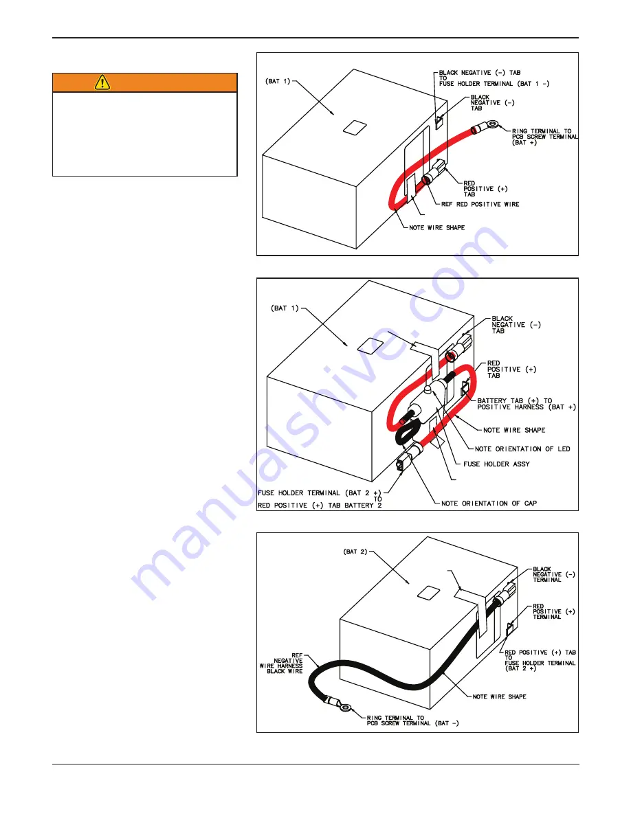
Figure 7 - Positive Harness to Battery 1

Figure 9 - Negative Harness to Battery 2

Figure 8 - Fuse Holder Assembly to Battery 1

WARNING

Improperly  disconnecting  or 

reconnecting  wires  can  lead  to 

electric-shock injury or damage 

to  the  PC  board.  Disconnect 

and  reconnect  wires  only  as 

instructed in this manual.

Refer  to  Figure  10,  page  7,  for  battery 

positioning  and  wire  orientation  inside 

POWERPac.
Note: 

Use tape to secure the wires to the bat-

teries (as shown in Figures 7-9). Place the 

tape in a location where the wire can sit flat 

against the battery. 
Also, when taping the fuse holder wire to the 

bottom of battery 2 (referenced, but not shown 

in Figure 8), do NOT tape over the loop fas-

tener on the bottom of battery 2. 
All connectors and ring terminals MUST be 

connected to the PC board screw terminals 

before the female terminals are connected to 

the battery tabs.
Set the new batteries in the lower housing with 

tabs facing up. Orient Battery 1 with tabs closer 

to PC Board side of housing, and Battery 2 with 

tabs closer to Actuator Port side of housing.

Connect  the  red  Batt  +  (positive)  wire 

1. 

(running from the PC board) to the battery 

1 positive terminal (red tab) (Figure 7). 

Use 3˝ tape to secure wire to battery 1.

Attach  battery  1  securely  to  the  lower 

2. 

housing with the hook-and-loop fastener. 

Orient the battery as shown in Figure 10, 

page  7  with  the  terminals  near  the  PC 

board end of the bottom housing.
Connect the fuse holder’s positive wire to 

3. 

the battery 2 positive terminal (red tab). 

Use 3˝ tape to secure wire to battery 2, 

careful not to tape over loop fastener on 

bottom of battery.
Attach battery 2 securely to the housing 

4. 

with the hook-and-loop fastener. Orient 

the battery as shown in Figure 10, page 7 

with the terminals near the actuator port 

end of the bottom housing.
Connect the fuse holder negative wire to 

5. 

the battery 1 negative terminal (black tab) 

(Figure 8). Use 3˝ tape to secure wire to 

battery 1.
Connect the black Batt - (Negative) wire 

6. 

(running from the PC board) to the battery 

2 negative terminal (black tab) (Figure 9). 

Use 3˝ tape to secure wire to battery 2.

˝

USE 3  TAPE TO SECURE WIRE TO BATTERY

˝

USE 3  TAPE TO 

SECURE WIRE 

TO BATTERY   

˝

˝

Summary of Contents for 082-2012

Page 1: ...formation Notices with the signal word Important emphasize important usage or maintenance information Notices with the signal word WARNING indicate a poten tially hazardous situation which if not avoi...

Page 2: ...on pages 3 through 8 to replace your batteries TheVersion 3 POWERPac is the only POWERPac with the battery charging light test light and test button on top as shown in Figure 2 and two control cable...

Page 3: ...ectors to unplug the wires Instructions in this section are for replacing the batteries inside a Version 3 POWERPac If you have a Version 1 or 2 POWERPac see Section 3 pages 9 12 to replace your batte...

Page 4: ...and PC board Open the POWERPac using a 1 Phillips screwdriver and 4 11 32 wrench to remove the 12 screws and nuts If you wish to separate the upper and lower housings 5 remove the wires listed below f...

Page 5: ...looped fastening strip at tached and that the case has two hooked strips attached 1 Inspect the hooked strips in the case If they are clean undamaged and held the old batteries in place securely skip...

Page 6: ...in the lower housing with tabs facing up Orient Battery 1 with tabs closer to PC Board side of housing and Battery 2 with tabs closer to Actuator Port side of housing Connect the red Batt positive wi...

Page 7: ...ce contact Ferno Customer Service EMSAR or your Ferno distributor page 13 Gather all harnesses from the upper housing and coil to 5 gether above the PC board as the upper housing is placed onto the lo...

Page 8: ...roperly Figure 12 Battery Condition Light Condition Light 2 8 Verify the Installation 1 Make sure power is OFF 2 Put the POWERPac in place beneath the backrest and at tach the Control and Actuator cab...

Page 9: ...y rings watches bracelets etc before working inside the POWERPac Jewelry can cause an electrical short damaging the POWERPac When plugging in a wiring connector always push the connector straight onto...

Page 10: ...This could damage the battery or cause a spark Batt 2 Batt 1 3 3 Open the POWERPac 1 Turn the cot power switch OFF 2 Disconnect the Control Unit cable and Actuator Unit cable from the POWERPac If you...

Page 11: ...tive terminals on a battery This could damage the battery or cause a spark 3 5 Replace the Hooked Fastening Strips If Needed Verify that each new battery has a looped fastening strip at tached and tha...

Page 12: ...s not function properly contact Ferno Customer Relations EMSAR or your Ferno distributor for service page 13 3 7 Close the POWERPac Housing Note Make sure both circuit breakers are not tripped before...

Page 13: ...tions Customer service and product support are important aspects of each Ferno product For assistance or infor mation Canada and the U S A Telephone Toll free 1 877 733 0911 Telephone 1 937 382 1451 F...

Page 14: ......

Reviews: