7
© Ferno-Washington, Inc. 234-3388-01 June 2008
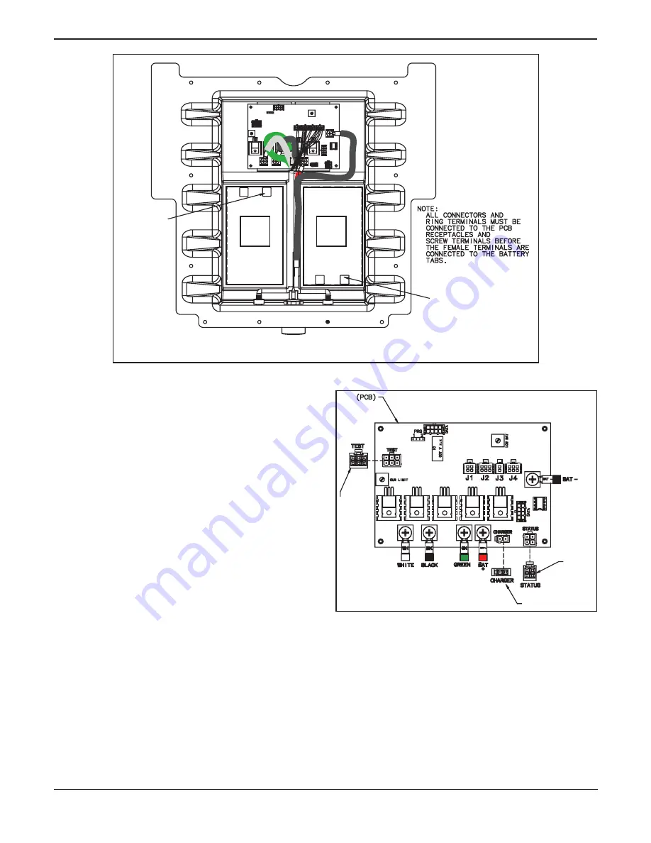
Figure 10 - Installing Batteries
2.6 Close the POWERPac
If disconnected, reconnect test wire (6-pin) to the PC board
1.
(Figure 11).
If disconnected, reconnect charger wire (2-pin) to the PC
2.
board (Figure 11).
If disconnected, reconnect status wire (4-pin) to the PC
3.
board (Figure 11).
Push the Battery Test button on top of the POWERPac.
4.
See
Test the Batteries
on page 8. If the battery test light is
green or yellow, continue to step 5.
If the battery test light is red or there is no light, inspect
the wire connections from the batteries to the PC board.
If all wire connections appear to be good, the fuse may be
blown (see
POWERPac Users Manual
for fuse replace-
ment instructions). For assistance, contact Ferno Customer
Service, EMSAR or your Ferno distributor (page 13).
Gather all harnesses from the upper housing and coil to-
5.
gether above the PC board as the upper housing is placed
onto the lower housing. Ensure no wire or connector is
trapped between the housings, gasket or batteries.
Align the 12 screw holes in the upper and lower housings
6.
of the POWERPac.
Note:
Assemble the housing with the screws at the top of the
upper housing and the nuts under the lower housing.
Close the POWERPac using a #1 Phillips screwdriver
7.
and 11/32˝ wrench to insert the 12 screws and nuts into
the case.
Figure 11 - PC Board Connections
(Upper Housing Wires)
(Note: Wires Removed For Clarity)
TEST
WIRE
(6-PIN)
CHARGER WIRE (2-PIN)
STATUS
WIRE
(4-PIN)
Batt
2
Batt
1
Accessory Kit 082-2012
TAB END
TERMINALS
BATTERY 1
TAB END
TERMINALS
BATTERY 2
NOTE: ONCE WIRES ARE ATTACHED, bATTERIES ARE ORIENTED
WITH THE TAbS fACING THE CENTER Of THE HOuSING
Summary of Contents for 082-2012
Page 14: ......


