background image

EN

10

Move the machine carefully and avoid sudden movements 
which could unbalance the load and make it drop.
To remove the machine from the plate after packing removal,  
loosen the fi xing screws but keep them should the machine 
be transported for long stretches.
To transport the machine after freeing it from the plate,secure it 
with resistant chains, ropes or braces,  by passingthem through 
the the eyebolts provided.

Then the  machine must be lifted using a hoist of adequate 
capacity or through another means suitable for this purpose.


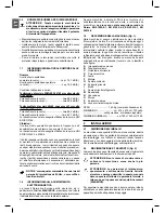
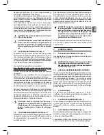
WARNING: Do not lift the machine by the body D 
(Fig. 1).


WARNING: Before lifting the machine, check that 
the body is lowered and secured to the rest of the 
structure by means of ropes or other claming means 
as shown in Fig. 2         

 2.3 

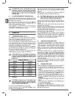
ELECTRICAL CONNECTIONS (Fig. 3)

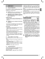
Check that the mains to which the machine is connected is 
earthed in accordance with current safety regulations and that 
the  power point is in good condition. 
Connect a plug in compliance with safety rules to the end 
of the mains cable of the machine, checking that the yellow/
green protective conductor is fi tted into the relative terminal 
marked.

Check for the correct polarity of the motor through the blade 
which must rotate 

in the direction shown by the arrow 

present on the machine body. If this is not the case, invert two 
of the three cables of the plug. 
Mount electric panel 

A

 into its seat on the pivoting support, and 

fi nally secure it by tightening the supplied fi xing screws.
Remember that there should be a magnetothermic protective 
device fi tted upstream of the mains to protect all the conductors  
from short circuits and overloads.
This protective device should be selected according to the 
electrical features of the machine stated on the motor.
 
In case of voltage failure in the system, you can wait for 
the connection to be restored without danger of hazardous 
conditions. In fact, the electric panel is equipped with a 
reset function which prevents the machine from restarting 
automatically.
To restart the machine, press the button 

C (Fig. 4)

 and then 

push button 

(Fig. 4) on the handgrip.


WARNING: Never change  the overload cutout 
setting to avoid overloads which could damage the 
motor circuits and other mechanical members.

 2.4 

POSITION/WORK STATION (Fig. 5)

Position the machine by moving it as described in  paragraph 
2.2 on to a suffi ciently level bench, in such a way that the coolant 
can refl ow in the collecting tank during the cutting operations. 
Taking the ergonomic criteria into consideration, the ideal height 
shall be that which enables you to position the table between 
90 and 95 centimetres from  the fl oor

 (see Fig. 2)

Now, cut the strap which holds the body lowered  and remove 
the  wooden cap which protects the machine  while in transit. 


CAUTION:   Make sure that the machine is placed 
in a working area with suitable environmental 
conditions and lighting. The general  conditions 
of the  working environment are of fundamental 
importance for accident prevention.

Now lift the machine body and fi t the eye of spring 

A

 into its 

location on pin 

B

 to prevent the spring from being expelled.

 3 ADJUSTING


3.1 

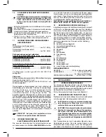
TENSION OF THE BLADE  (Fig. 4)

Turn the handwheel clockwise 

B

 till the green indicator lights 

C

 up. 


WARNING:  The tensioning device is equipped 
with  a safety microswitch which prevents the 
machine from operating  till the blade is tensioned 
correctly.  

 3.2 

BAR STOP (OPTIONAL) 

Use the bar stop supplied if you have to do several cuts on  
pieces of the same length. 
In this way you do not have to  repeat the same measurement 
each time.
Before adjust the bar stop, be sure the main switch is in 0 
position.
Screw rod into the hole of the vice and fasten it with  nut Slacken 
the handwheel and place the stop at the correct distance from 
the blade. Tighten handwheel again.

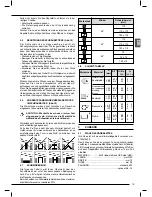
 3.3 CUTTING 

ANGLE

The machine can effect cuts ranging from  0° to 60°.
To unlock the body rotation, release the handle on the rotating 
support.

3.4 

CUTTING SPEED (Fig. 3)

Depending on the type of material and its section (see 
CUTTING TABLE) you can choose two different cutting speed 
30 or 60 m/min. by means of the switch 

N

.

 3.5 

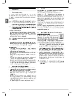
SLIDING BLADE GUIDE (Fig. 3)

The sliding blade guide 

D

 with integrated protection fi tted on 

your sawing machine is used to perform the cut while guiding 
the necessary part of the blade and fully protecting the part 
not used in the cutting process. Slacken the knob 

and slide 

the blade guide 

so as to move it closer to or further from the 

part to be cut, as shown in the fi gure.


WARNING: If this adjustment is not done, the part 
of the blade not used in the cutting process will be 
exposed and this will create an extra risk of contact, 
besides altering the quality of the cut.

Summary of Contents for 2201 SPECIAL

Page 1: ...BRAUCHSANLEITUNGEN UND WARTUNG MODE D EMPLOI ET ENTRETIEN INSTRUCCIONES PARA EL USO Y MANUTENCION INSTRU ES DE UTILIZA O SEGATRICE A NASTRO BAND SAW MACHINE BANDS GEMASCHINE SCIE A RUBAN SIERRA DE CIN...

Page 2: ......

Page 3: ...rom the original manuale tradotto dall originale 8 14 DEUTSCH DE bersetzung der Originalausgabe des Handbuchs manuale tradotto dall originale 15 21 FRANCAIS ES Manuel traduit partir de l original manu...

Page 4: ......

Page 5: ...icoloditrascinamento taglio 1 4 TIPO DI IMPIEGO E CONTROINDICAZIONI Questa macchina e stata progettata e realizzata per il taglio dei metalli Essa pu tagliare ACCIAI COMUNI FE 37 ACCIAI SPECIALI C 40...

Page 6: ...ri 1 8 INFORMAZIONI SULLA COMPATIBILITA ELETTROMAGNETICA Le recenti Normative Europee sulla sicurezza ed in particolare la Direttiva 2004 108 CE prescrivono che tutte le apparecchiature siano dotate d...

Page 7: ...er alcun motivo la taratura del salvamotore per evitare che i sovraccarichi possano danneggiare i circuiti del motore ed altri organi meccanici 2 4 POSIZIONAMENTO POSTO DI LAVORO Fig 5 Posizionate la...

Page 8: ...vo sul pezzo e completate il taglio Fra un taglio ed un altro nella fase di posizionamento del pezzo rilasciate sempre il pulsante non cercate di bloccarlo o di alterarne in alcun modo le caratteristi...

Page 9: ...interposizione di altri oggetti ATTENZIONE Non tenete mai i pezzi da tagliare in mano Quando il taglio riguarda i profilati piatti o sagome particolari fate riferimento agli esempi di figura Se lo spe...

Page 10: ...riparazione in garanzia dovete sempre presentare assieme alla macchina la ricevuta fattura di acquisto L assenza di tale certificato invalida la garanzia applicata alla macchina Nel caso sia necessar...

Page 11: ...ulata La lama tende ad uscire dalle guide Fate controllare la macchina da personale specializzato non tentate di riparare il motore da soli Controllate l integrit dei fusibili e sostituiteli se necess...

Page 12: ...with the tool operating Danger of dragging cutting 1 4 RECOMMENDED AND NOT RECOMMENDED USAGE This machine has been designed and developed for cutting metals It can cut COMMON STEELS FE 37 SPECIAL STEE...

Page 13: ...nds away from the working areas while the machine is moving before loadingorunloadingthepart releasetherunbutton on the hand grip Always keep processing residues away from the cutting area Always use...

Page 14: ...2 4 POSITION WORK STATION Fig 5 Position the machine by moving it as described in paragraph 2 2ontoasufficientlylevelbench insuchawaythatthecoolant can reflow in the collecting tank during the cuttin...

Page 15: ...coils reaches the threshold limit defined by the insulation class to prevent damage to the motor In this case release the button and wait for automatic reset which usually takes place after a few min...

Page 16: ...pieces to be cut in your hand When the pieces to be cut are profiled sections flat pieces or special shapes refer to the examples shown in the figures If the thickness of the profiled section is to be...

Page 17: ...posed on the user if the appliance is disposed 6 MAINTENANCE 6 1 ROUTINE MAINTENANCE The interventions of routine maintenance which can also be carried out by unskilled personnel are described in this...

Page 18: ...or corrugated Thebladetendstoprotrude from the guides Specialized personnel should check the machine do not attempt to repair the motor by yourself Check fuse integrity and replace if necessary Check...

Page 19: ...nzugs Schnitt 1 4 EINSATZBEREICH UND UNGEEIGNETER EINSATZ DieseMaschinewurdezumSchneidenvonMetallenkonzipiert und gebaut Geeignet zum S gen von NORMALSTAHL FE 37 SPEZIALSTAHL C 40 18NiCrMo5 ALUMINIUM...

Page 20: ...neuesten Europ ischen Sicherheitsbestimmungen und insbesondere die Richtlinie 2004 108 EWG schreiben vor da alle Apparate mit Schutzeinrichtungen gegen Funkst rungen von und in die Au enumgebung ausg...

Page 21: ...n k nnen 2 4 POSITIONIERUNG ARBEITSPLATZ Abb 5 DieMaschine wieinAbschnitt2 2beschrieben aufeinebenes Untergestell positionieren damit die K hlfl ssigkeit w hrend der Schneidarbeiten ordnungsgem in die...

Page 22: ...lich ausf llt ist das kein Grund zur Beunruhigung Der berhitzungsschutz hat in diesem Fall die Maschine ausgeschaltet um die Wicklungen des Motors vor Sch den zu sch tzen Dr cken Sie den Schalter im H...

Page 23: ...spannt ohne weitere Teile dazwischen anzubringen ACHTUNG Werkst cke m ssen immer fest eingespannt sein Halten sie die Werkst cke w hrend des Schneidens nie in den H nden Werkst cke mit besonderen Form...

Page 24: ...in Punkt 4 1 zu und sch tten Sie sie vorsichtig in den Beh lter damit nichts von diesem umweltbelastenden Produkt vergossen wird F r die Entsorgung der alten Emulsion siehe Punkt 6 4 6 3 SERVICE BeiRe...

Page 25: ...inem Fachmann pr fen Versuchen Sie nie den Motor selbst zu reparieren Pr fen Sie nach ob die Sicherungen intakt sind und wechseln Sie sie bei Bedarf aus Pr fen Sie nach ob Spannung im Stromnetz vorhan...

Page 26: ...mains dans cette zone lorsque l outil fonctionne Danger d entra nement coupe 1 4 TYPE D EMPLOI ET DE CONTRE INDICATIONS Cette machine a t con ue et r alis e pour le d coupage des m taux Elle peut cou...

Page 27: ...E POUR LES RISQUES RESIDUELS ATTENTION Tenez toujours les mains distance des zones d usinage quand la machine est en mouvement avant d effectuer toute op ration de chargement ou d chargement de la pi...

Page 28: ...pui D placer la machine avec une pr caution toute particuli re en faisant attention aux mouvements brusques qui pourraient causer le d s quilibre de la charge et sa chute cons quente Pour s parer la m...

Page 29: ...ercer une pression progressive sur la pi ce et achevez la coupe Entre une coupe et l autre durant la phase de positionnement de la pi ce rel chez toujours le bouton ne cherchez pas le bloquer et en au...

Page 30: ...ces couper doivent tre plac es directement entre les m choires D sans interposer d autres objets ATTENTION Ne tenez jamais les pieces a couper dans la main Quand la coupe s effectue sur des profil s d...

Page 31: ...r le point 6 4 6 3 ASSISTANCE Dans le cas de r paration sous garantie il faut toujours pr senter avec la machine le re u ou la facture d achat L absence de certificat invalide la garantie appliqu e la...

Page 32: ...d sortir des guides Faites contr ler la machine par des sp cialistes ne tentez pas de r parer le moteur sans aide Contr lez l int grit des fusibles et les remplacer si n cessaire Contr lez la pr sence...

Page 33: ...as manos en esta zona herramienta en funcionamiento Peligro de arrastre corte 1 4 MODO DE EMPLEO Y CONTRAINDICACIONES Esta m quina se ha proyectado y realizado para cortar metales Esta puede cortar AC...

Page 34: ...estinados bajo la peana de apoyo 1 6 NORMAS DE SEGURIDAD POR LOS RIESGOS RESIDUOS CUIDADO Mantenga siempre las manos lejos de la zona de trabajo mientras la m quina est en funci n antes de realizar cu...

Page 35: ...de marcha A Fig 4 situado en la empu adura CUIDADO No modifiquen bajo ning n motivo el calibrado del protector contra sobrecargas para evitar que las sobrecargas puedan perjudicar los circuitos del mo...

Page 36: ...l corte Erntre un corte y otro en la fase de colocaci n de la pieza suelte siempre el pulsador y no intente bloquearlo no debiendo alterar de ninguna manera las caracter sticas funcionales Si despu s...

Page 37: ...EZA EN EL TORNO Fig 10 Hay que introducir las piezas a cortar directamente entre las mordazas D sin que otros objetos se interpongan CUIDADO No lleve nunca las piezas a cortar en la mano Cuando hay qu...

Page 38: ...odo de garant a se deber presentar siempre junto con la m quina el recibo factura de compra La carencia de dicho certificado invalida la garant a aplicada a la m quina En el caso de que sea necesario...

Page 39: ...orte basto u ondulado La hoja tiende a salir de las gu as Hagan que personal especializado controle la m quina ni intenten reparar el motor sin ayuda Controlen que los fusibles est n en buen estado y...

Page 40: ...introduzir as m os nesta zona com a m quina a funcionar Perigo de ficar preso corte 1 4 TIPO DE UTILIZA O E CONTRA INDICA ES Estam quinafoiconcebidaefabricadaparaocortedemetais Esta pode serrar A OS...

Page 41: ...e o uso de meios pessoais de protec o dos ouvidos tais como toucas ou tamp es auriculares 1 8 INFORMA ES SOBRE A COMPATIBILIDADE ELECTROMAGN TICA As recentes Normativas Europeias sobre a seguran a e e...

Page 42: ...igar novamente a m quina necess rio premir o bot o C Fig 3 e o bot o de arranque A Fig 4 situado no punho ATEN O N o modificar por nenhum motivo a regula o do dispositivo de protec o do motor para evi...

Page 43: ...no motor Neste caso largar o bot o e esperar o restabelecimento autom tico que geralmente se d ap s alguns minutos 4 3 RODAGEM DA L MINA Para se obter o melhor rendimento as l minas bimet licas que s...

Page 44: ...igura Se a espessura do perfil for muito fina para evitar o seu esmagamento entre as garras do torno melhor introduzir no interior do perfil um molde que encha o perfil 4 8 TABELA DE CORTE 90 45 60 17...

Page 45: ...No caso de repara o durante a garantia necess rio apresentar o recibo ou factura de compra juntamente com a m quina A aus ncia desse certificado caduca a garantia aplicada na m quina Caso seja necess...

Page 46: ...u ondulado La hoja tiende a salir de las gu as Hagan que personal especializado controle la m quina ni intenten reparar el motor sin ayuda Controlen que los fusibles est n en buen estado y sustit yan...

Page 47: ...www femi it...

Page 48: ...6 90 14 62 40024 Castel San Pietro Terme BO ITALIA Via Salieri 33 35 Tel 39 051 941866 Fax 39 051 6951332 E Mail infocom femi it http www femi it...

Reviews: