background image

Σ

YG-S7G2-43C-MDK User’s 

Manual 


11/18/2015 

Copyright ©2015,  

Future Designs, Inc 

Page 

8

 of 

28


1.5


Requirements 

 The 

Σ

YG-S7G2-43C -MDK requires a carrier board with a 200-pin SO-DIMM socket.  The 

socket should have the key at the 1.8V location. The CARRIER Board from Future Designs 
provides this socket and should be utilized to develop your application for initial verification. 
Each 

yG development kit includes:  


Σ

yG-S7G2 System on Module (SOM) 


Renesas Synergy Software Platform 


Carrier Board 


5 VDC, 2.3A North American Power Supply 


USB and Ethernet Cables 


Segger ARM Cortex-M Mini-JTAG debugger and cables  


Optional LCD Carrier Board 


Optional 4.3” or 7.0

 PCAP Touch Screen LCD 


1.6


Σ

yG-S7G2 SOM Power Requirements 

The power requirement for the 

Σ

YG-S7G2-43C-MDK is 5V DC Center Positive 2A Power 

Supply. 


Getting Started 

2.1


Setting up the Hardware 

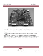
The SOMDIMM should be inserted into the DIMM Socket as shown below and then 

locked into place by pushing down to the Carrier Board. Ensure the SOMDIMM is inserted 
completely into the socket prior to locking. The socket utilized on the CARRIER Board is 
rated for a minimum of 25 insertions. 

Summary of Contents for SYG-S7G2-43C-MDK

Page 1: ...Copyright 2015 Future Designs Inc All Rights Reserved User s Manual YG S7G2 43C MDK...

Page 2: ...anical for any purpose without the express written permission of Future Designs Inc 996 A Cleaner Way Huntsville AL 35805 NOTE The inclusion of vendor software products in this kit does not imply an e...

Page 3: ...Getting Started 8 2 1 Setting up the Hardware 8 2 2 Demonstration Software 10 yG S7G2 SOM System on Module Board Components 12 3 1 ARM Mini JTAG J2 12 3 2 Tag Connect J7 13 3 3 MicroSD Socket J1 14 3...

Page 4: ...nual 11 18 2015 Copyright 2015 Future Designs Inc Page 4 of 28 4 9 External I2S Audio 25 yG S7G2 System on Module Board SOM Layout 26 3 1 Schematics 26 3 2 Mechanicals 26 Support 28 6 1 Where to Get H...

Page 5: ...esas Synergy GUI The yG S7G2 Modular Development Kit for the System on Module is the gateway for beginning Renesas SynergyTM projects The yG S7G2 Modular Development Kit is compatible with FDI s yG Mo...

Page 6: ...YG S7G2 43C MDK User s Manual 11 18 2015 Copyright 2015 Future Designs Inc Page 6 of 28 1 3 Renesas Synergy S7G2 Microcontoller Block Diagram Figure 1 S7G2 System Block Diagram...

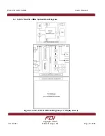
Page 7: ...YG S7G2 43C MDK User s Manual 11 18 2015 Copyright 2015 Future Designs Inc Page 7 of 28 1 4 yG S7G2 43C MDK System Block Diagram Figure 2 YG S7G2 Kit Block Diagram 4 3 display shown...

Page 8: ...latform Carrier Board 5 VDC 2 3A North American Power Supply USB and Ethernet Cables Segger ARM Cortex M Mini JTAG debugger and cables Optional LCD Carrier Board Optional 4 3 or 7 0 PCAP Touch Screen...

Page 9: ...Verify the LCD Interface ribbon cable connects the LCD CARRIER board to the CARRIER J7 board 3 With the power off plug the 5V center positive Power Supply into 5V P5 of the CARRIER board 4 Connect an...

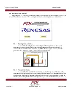
Page 10: ...he demonstration software start menu The purpose of the Brewing Demonstration is to showcase Renesas SSP s sprite animation capability Bottles appear to move down the production line fill with a liqui...

Page 11: ...ode comments and annotations to be written in a certain manner and then compiled along with source code into HTML documentation FDI provides the pre compiled HTML documentation at this link http www t...

Page 12: ...ctions for the tool chain are included in the e2 studio ISDE download NOTE Access to this site is restricted to authorized Renesas Synergy beta program participants If you require access to this site...

Page 13: ...e Designs Inc Page 13 of 28 3 2 Tag Connect J7 Use the Tag Connect 10 pin cable to program and JTAG the yG S7G2 SOM using a Segger J Link device Cable http www tag connect com tc2050 arm2010 Cable htt...

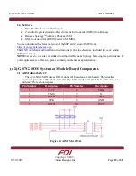
Page 14: ...CMD SDI 4 VDD 5 CLK SCLK 6 VSS 7 DAT0 SDO 8 DAT1 RSV 9 CD The microSD card must be removed using the spring loaded push pull mechanism on the microSD socket Forceful removal of a microSD card will res...

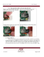
Page 15: ...itioning it with its text facing up Position the ridge or lip of the card furthest from the socket Next partially insert the card into the socket Then use your figure to gently push the card into the...

Page 16: ...or sides of the microSD card to gently pull it out The microSD card is now fully removed from the socket 3 4 Ethernet PHY U5 The yG S7G2 SOM provides an Ethernet PHY from SMSC LAN8720 The LAN8720 is a...

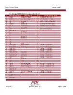
Page 17: ...ble O Connected to S7G2 Port 2 bit 0 26 GPIO26_LCDLE LCD Latch Enable O Connected to S7G2 Port 2 bit 1 27 GPIO27_LCDCLK LCD Clock O Connected to S7G2 Port 2 bit 2 28 GPIO28_LCDFP O Connected to S7G2 P...

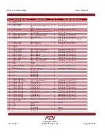
Page 18: ...6 74 GPIO74_SDA GPIO User IO I2C Bus SDA B Connected to S7G2 Port 0 bit 27 75 GPIO75_SCL GPIO User IO I2C Bus SCL O Connected to S7G2 Port 0 bit 28 76 GND Ground P 77 GND Ground P 78 GPIO78_ACC_IRQ GP...

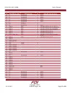
Page 19: ...onnected to S7G2 Port 2 bit 22 121 GPIO121 GPIO B Connected to S7G2 Port 2 bit 23 122 GPIO122 GPIO B Connected to S7G2 Port 2 bit 25 123 GPIO123_SPKR_DA0 GPIO O Connected to S7G2 Port 2 bit 26 SPEAKER...

Page 20: ...nected U Unused 174 NC Not connected U Unused 175 NC Not connected U Unused 176 NC Not connected U Unused 177 NC Not connected U Unused 178 NC Not connected U Unused 179 NC Not connected U Unused 180...

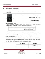
Page 21: ...ice The CARRIER Board includes one USB Device Interface allowing the unit to be connected to a USB Host such as a PC Through this connection the CARRIER represents a peripheral to the USB Host The ope...

Page 22: ...e software utilized i e driver support Please refer to the specific details of the processor module being utilized for support of the USB Host function D3 indicates VBUS power is good for the USB Host...

Page 23: ...speed transceiver IC to provide fully ISO 11898 standard interface at up to 1MBaud The TJA1040 allows up to 110 nodes and very low electromagnetic emissions Note Rev 1 PCB only supports CAN on P3 Plea...

Page 24: ...CARRIER Board and RXD is an INPUT to the CARRIER Board Note Rev 1 PCB only supports DCE on P4 Please refer to the specific details of the processor module being utilized for support of the RS232 Seria...

Page 25: ...module for connectivity details 4 9 External I2S Audio The Rev 1 CARRIER board provides an external I2S Audio Expansion Connector Please refer to the specific details of the processor module for conne...

Page 26: ...5 Future Designs Inc Page 26 of 28 yG S7G2 System on Module Board SOM Layout 3 1 Schematics Visit this link for schematics of the SYG S7G2 SOM http www teamfdi com wp content uploads SYG S7G2 SOM pdf...

Page 27: ...YG S7G2 43C MDK User s Manual 11 18 2015 Copyright 2015 Future Designs Inc Page 27 of 28 Figure 8 Carrier Board Top...

Page 28: ...ailable at http www teamfdi com support 6 2 Useful Links Future Designs Inc Forums http www teamfdi com post_type forum SYG S7G2 MDK Product Page http www teamfdi com product details syg s7g2 43c mdk...

Reviews: