


Σ
YG-S7G2-43C-MDK User’s
Manual
11/18/2015
Copyright ©2015,
Future Designs, Inc
Page
18
of
28
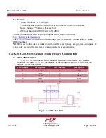
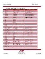
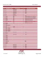
Pin
SOMDIMM Signal Name
Application Details
I/O
SOMDIMM Connection Details
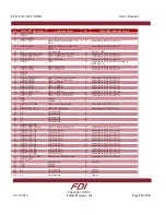
54
GPIO51_SPCK
55 GPIO55
56
GPIO56_MOSI
57
GPIO57_TXD
GPIO / Serial Transmit Data – For
RS232
O
Connected to S7G2 Port 0 bit 10
58
GPIO58_RXD
GPIO / Serial Receive Data – For
RS232
I
Connected to S7G2 Port 0 bit 11
59
NC
Not connected
U
DO NOT USE!
60
GPIO60_USBD_UPLED
GPIO / USB Device Up LED
O
Connected to S7G2 Port 0 bit 13
61
GPIO61_USBD_CON
GPIO / USB Device Connect
O
Connected to S7G2 Port 0 bit 14
62
GPIO62_RSCK
GPIO / SPI Clock
O
Connected to S7G2 Port 0 bit 15
63
GPIO63
GPIO
O
Connected to S7G2 Port 0 bit 16 (used for
EEPROM CS)
64
GPIO64_MISO
GPIO / SPI MISO
I
Connected to S7G2 Port 0 bit 17
65
GPIO65_MOSI
GPIO / SPI MOSI
O
Connected to S7G2 Port 0 bit 18
66
GPIO66
67 GPIO67
68
GPIO68_USBH_OVC
GPIO / USB Host Over Current
I
Connected to S7G2 Port 0 bit 21
69
GPIO69_TPIRQ
GPIO / Touch IC IRQ Input
I
Connected to S7G2 Port 0 bit 22
70
GPIO70_AD0.0
GPIO / AD0 Bit 0
I
Connected to S7G2 Port 0 bit 23
71
GPIO71_AD0.1
GPIO / AD0 Bit 1
I
Connected to S7G2 Port 0 bit 24
72
GPIO72_AD0.2
GPIO / AD0 Bit 2
I
Connected to S7G2 Port 0 bit 25
73
GPIO73_AD0.5_DA1
GPIO / AD0 Bit 3
I
Connected to S7G2 Port 0 bit 26
74
GPIO74_SDA
GPIO / User IO I2C Bus SDA
B
Connected to S7G2 Port 0 bit 27
75
GPIO75_SCL
GPIO / User IO I2C Bus SCL
O
Connected to S7G2 Port 0 bit 28
76
GND
Ground
P
77 GND
Ground
P
78
GPIO78_ACC_IRQ
GPIO / Accelerometer IRQ
I
Connected to S7G2 Port 1 bit 2
79 NC
80
GPIO80_RTC_IRQ
GPIO / RTC IRQ Input
I
Connected to S7G2 Port 1 bit 5
81 NC
Not
connected
U
82
NC
Not connected
U
83 NC
Not
connected
U
84
NC
Not connected
U
85 NC
Not
connected
U
86
GPIO86_LED_BR
87
GPIO87_USBH_PPWR
GPIO / USB Host Power Ctl
O
Connected to S7G2 Port 1 bit 19
88
GPIO88_LCD_G2
LCD Data Bit 10
O
Connected to S7G2 Port 1 bit 20
89
GPIO89_LCD_G3
LCD Data Bit 11
O
Connected to S7G2 Port 1 bit 21
90
GPIO90_LCD_G4
LCD Data Bit 12
O
Connected to S7G2 Port 1 bit 22
91
GPIO91_LCD_G5
LCD Data Bit 13
O
Connected to S7G2 Port 1 bit 23
92
GPIO92_LCD_G6
LCD Data Bit 14
O
Connected to S7G2 Port 1 bit 24
93
GPIO93_LCD_G7
LCD Data Bit 15
O
Connected to S7G2 Port 1 bit 25
94
GPIO94_LCD_B4
LCD Data Bit 16
O
Connected to S7G2 Port 1 bit 26
95
GPIO95_LCD_B5
LCD Data Bit 17
O
Connected to S7G2 Port 1 bit 27
96
GPIO96_LCD_B6
LCD Data Bit 22
O
Connected to S7G2 Port 1 bit 28
97
GPIO97_LCD_B&
LCD Data Bit 23
O
Connected to S7G2 Port 1 bit 29
98
GPIO98_USBD_VBUS
USB Device VBus Sense Input
I
Connected to S7G2 Port 1 bit 30
99 GPIO99_AD0
100
NC
Not connected
B
Unused
101 GND
Ground
P
102
GND
Ground
P
103 NC
Not
connected
U Unused
104
NC
Not connected
U
Unused
105 NC
Not
connected
U Unused


