


Σ
YG-S7G2-43C-MDK User’s
Manual
11/18/2015
Copyright ©2015,
Future Designs, Inc
Page
24
of
28
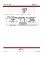
4.7
RS232
The CARRIER Board includes one RS232 Serial Port Connector. This connector is a Male
DB9 configured as either DCE or DTE (Rev 2 and later only) depending on the configuration of
jumper block JP3. The interface includes optional RTS & CTS handshaking signals that are
brought to test points that the user may connect as needed (see page 5 of the schematic). Please
verify proper connectivity of this connector to the proper TXD<>RXD orientation. TXD is an
OUTPUT from the CARRIER Board and RXD is an INPUT to the CARRIER Board.
Note: Rev 1 PCB only supports DCE on P4
Please refer to the specific details of the processor module being utilized for support of the RS232
Serial Port function.
Pin Number
DCE Mode
DTE Mode
(Rev 2 and later only)
1
No Connect
No Connect
2
TXD (Output)
RXD (Input)
3
RXD (Input)
TXD (Output)
4
No Connect
No Connect
5
Signal Ground
Signal Ground
6
No Connect
No Connect
7
(OPT) RTS
(OPT) RTS
8
(OPT) CTS
(OPT) CTS
9
No Connect
No Connect
4.8
External I2C
The CARRIER board provides an external I2C connector for users to connect to the I2C bus
of the microprocessor.
CARRIER Rev 1
Pin Number
Description
1 3.3V
2 Signal
Ground
3 GPIO67_ESCL
4 GPIO66_ESDA
CARRIER Rev 2 and later
Pin Number
Description
1 5V
2 5V
3 3.3V
4 3.3V


