


Subject to change without notification
Subject to change without notification
8
3. Control
The module may be controlled using two different methods:
1. Electrically via the pins or via the built-in potentiometers. The speed of the drive
is proportional to either an applied analog voltage or an applied pulse train.
2. The serial interface accepts user-generated commands. Simple externally generated
commands permit a much more detailed control than is possible via the pins.
Control via electrical signals is described in Chapters
3.1
and
3.2
. Control via the programma-
ble interface is covered in Chapter
3.3
.
3.1 On the Module
On the module there are three potentiometers, with which the Acceleration Ramps, Output
Voltage and Speed can be set manually.
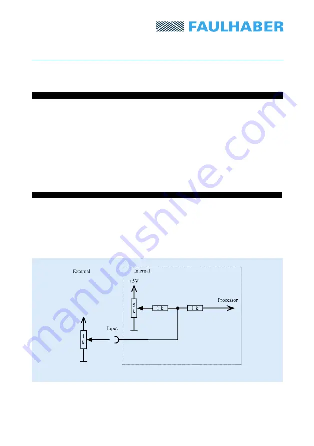
The outputs of these potentiometers are connected, via 1 k
Ω
resistors, to the analog inputs
of the microcontroller. Hence, these inputs can also be controlled via external potentiometers
(in this situation, the crosstalk will be minimized if the potentiometers on the module are set
to the middle of their range).
The relevant external pins are
RPM 1
,
Output Voltage 1
and
Ramp Slope
.
Fig. 5: Input switching with internal potentiometer
Warning:
If the voltage on an input is very close to 0V, the Analog/Digital converter will
register a 0. Then a voltage variation on the other input will produce no change in rotational
speed, since the two inputs are multiplied together internally. For such voltage variations to
produce an effect, both voltages must be sufficiently far from 0V (at least 5 mV) so that a
value different from 0 can be read.


