


2010-06-30
Page 22 of 42
IT430_Tech_doc.doc
■
Common EEPROM data formats (STMicroelectronics, M24M01 128 kB device)
■
Typical data lengths (c in/data out) of several bytes
■
Standard I²C bus maximum data rate 400kbps
■
Minimum data rate 100kbps
4.8 Time Mark TM
The TM output signal provides pulse-per-second (PPS) output pulse signal for timing purposes.
Pulse length (high state) is 200ms about 1us accuracy synchronized at rising edge to full UTC
second.
The firmware may support optionally other output functions from TM signal, like GPS_ON output
for e.g. external LNA power control or RTC_CLK, which outputs buffered RTC clock signal at
32768 Hz; contact Fastrax support for details.
4.9 WAKEUP
The WAKEUP output signal provides indication to e.g. external power supply when full power is
required by the module. Polarity is active high = high current mode. The external power supply
should be able to provide full current to VDD within 9ms after WAKEUP low->high transition.
WAKEUP signal can be also used externally to switch off the Active Antenna Bias supply voltage
(VDD_ANT) during Hibernate state; polarity is active high = VDD_ANT active.
4.10 Interrupt inputs EIT and EIT2
The EIT and EIT2 are external, level sensitive interrupt inputs. EIT2 pin is also configurable as an
edge-sensitive input. Both pins are disabled at initial power-up and usage is configured by the
software.
Either pin can be used as a source of a level sensitive interrupt to wake-up the module from
Hibernate low-power state. This feature allows external sensors, e.g. gyro, accelerometer,
compass, etc., to provide an interrupt when a change of state is detected.
4.10.1
EIT
The EIT signal is only available as a level triggered interrupt. Either high and low levels are
programmable as the active condition on EIT, this is also the same as the EIT2 pin. The input can
be left not connected when not used.
In order to recognize a level triggered interrupt, the EIT pin input must remain in a given state for
a long enough time for the RTC re-timing process to sample the level, 3 RTC_CLK ticks are
sufficient, about 90
µ
s. At system reset, the EIT pin is disabled.
Summary of Contents for IT430
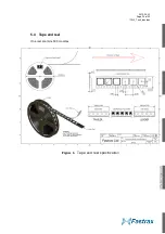
Page 24: ...2010 06 30 Page 24 of 42 IT430_Tech_doc doc Figure 3 Dimensions ...
Page 38: ...2010 06 30 Page 38 of 42 IT430_Tech_doc doc 7 3 Circuit drawing ...
Page 40: ...2010 06 30 Page 40 of 42 IT430_Tech_doc doc 7 6 Artwork layer 2 7 7 Artwork layer 3 ...
Page 41: ...2010 06 30 Page 41 of 42 IT430_Tech_doc doc 7 8 Artwork layer 4 Bottom ...


