


2010-06-30
Page 17 of 42
IT430_Tech_doc.doc
ON_OFF interrupts sent every second until the host port messages are outputted and/or
WAKEUP output is at high state.
When power supply is intended to be removed, it is suggested that prior power removal a serial
message in binary (MID 205) or NMEA format ($PSRF117,16*0B<CR><LF>) is sent to module to
shut down firmware operations orderly. Otherwise e.g. external EEPROM may get corrupted if
power down happens in the middle of EEPROM writing, which may increase in TTFF. If external
EEPROM is also used for ROM patch code, the abrupt power removal may cause patch code
corruption that may end to system failure.
Second option for orderly shutdown is to send ON_OFF interrupt prior VDD removal. Operations
shutdown may take anything between 10 to 900 ms depending upon operation in progress and
messages pending and hence is dependent upon serial interface speed and host port type.
If it is likely that VDD supply will be removed abruptly, suggestion is to add external voltage
monitor to detect under voltage condition below 5% nominal supply voltage and to drive
RESET_N signal to reset condition (low state). This important especially when external EEPROM
or data storage at host is used. VDD supply off-time is suggested to be over 10 seconds to next
power up in order to clear all internal backup RAM content and to minimize risk for wrong backup
data.
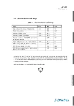
Main power supply VDD current varies according to the processor load and satellite acquisition.
Typical VDD peak current is 56 mA (typ.) during waking for Full on power up. Typical VDD
current in low power Hibernate state is 20uA. The external power supply can be using dual
low/high current modes, which can be controlled via the WAKEUP output signal (high current =
WAKEUP high) as indication when full power is required by the module. The external power
supply should be able to provide full current to VDD within 9 ms after WAKEUP low-to-high
transition.
The internal 1.2V regulator is powered from VDD supply and it boots for LDO mode. The internal
1.2V power supply includes also Switcher mode regulator (f = 8 MHz). The host may reduce
power drain by enabling the Switcher mode via sending a binary message from the host
(Message ID 178 TrackerIC, Sub ID 2 TrackerConfig; contact Fastrax support for details).
By-pass the VDD supply input by a low ESR ceramic de-coupling capacitor (e.g. 4.7 uF) placed
nearby VDD pin to ensure low ripple voltage at VDD. Ensure that the VDD supply ripple voltage
is low enough: 54 mV(RMS) max @ f = 0… 3MHz and 15 mV(RMS) max @ f > 3 MHz.
NOTE
VDD supply is intended to be active all the time. Abrupt
removals of VDD supply are not suggested and if required,
use an external voltage detector to force reset at VDD under
voltage conditions.
De-couple the VDD input externally with e.g. 4.7uF low ESR
ceramic capacitor connected to GND. The module has also
internal a low ESR (~0.01 ohm) by-pass capacitor at VDD
supply input. Ensure that the external regulator providing
VDD supply is suitable for loads with low ESR ceramic
capacitors.
Summary of Contents for IT430
Page 24: ...2010 06 30 Page 24 of 42 IT430_Tech_doc doc Figure 3 Dimensions ...
Page 38: ...2010 06 30 Page 38 of 42 IT430_Tech_doc doc 7 3 Circuit drawing ...
Page 40: ...2010 06 30 Page 40 of 42 IT430_Tech_doc doc 7 6 Artwork layer 2 7 7 Artwork layer 3 ...
Page 41: ...2010 06 30 Page 41 of 42 IT430_Tech_doc doc 7 8 Artwork layer 4 Bottom ...


