


2010-06-30
Page 19 of 42
IT430_Tech_doc.doc
■
The receiver FIFO is not empty
■
The receiver FIFO fill level does not exceed the alarm level
■
There are no received FIFO input for a programmable number of SPI source clock ticks
4.3.3 Host Port I
2
C
The I²C host port interface supports:
■
Operation up to 400kbps
■
Individual transmit and receive FIFO lengths of 64B
■
640
µ
S interrupt intervals when the FIFO fill point is programmed for 32B
■
Interrupts are available when the FIFO is empty / full or when there are error conditions
■
2 primary I²C modes exist:
■
Master transmit where module is master
■
Slave receive where module is slave
The operation of the I²C with a master transmit and slave receive mimics a UART operation,
where both module and host can independently freely transmit. It is possible to enable the master
transmit and slave receive at the same time,
4.4 ON_OFF control input
The ON_OFF control input must be used by the host to wakeup the module after first power
up and to control the receiver activity between Normal and Hibernate states and also to
generate interrupt in Push-to-Fix and SiRFAware modes of operation.
The module will boot to Hibernate state after power up. First ON_OFF interrupt wakes up
the module for Normal (Navigation) operation. Consequent ON_OFF interrupts switch the
operation mode between Hibernate and Normal modes.
The ON_OFF interrupt is generated by rising edge of a low-high-low toggle, which should be
longer than 90us and less than 1s (suggestion is abt. 100ms pulse length). Do not generate
ON_OFF interrupts less than 1 sec intervals. Especially take care that any multiple switch
bounce pulses are filtered out.
During Hibernate state the I/O Keep Alive is still active, thus I/O signals keep respective states
except TX and RX signals, which are configured to high input impedance state.
Summary of Contents for IT430
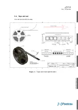
Page 24: ...2010 06 30 Page 24 of 42 IT430_Tech_doc doc Figure 3 Dimensions ...
Page 38: ...2010 06 30 Page 38 of 42 IT430_Tech_doc doc 7 3 Circuit drawing ...
Page 40: ...2010 06 30 Page 40 of 42 IT430_Tech_doc doc 7 6 Artwork layer 2 7 7 Artwork layer 3 ...
Page 41: ...2010 06 30 Page 41 of 42 IT430_Tech_doc doc 7 8 Artwork layer 4 Bottom ...


