


Table of Contents
23
2. 2 . 5
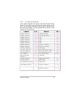
Connectors & Jumpers
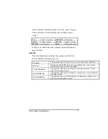
The connectors allow the CPU card to connect with other parts of the
system. Some problems encountered by your system may be a result
from loose or improper connections. Ensure that all connectors are in
place and firmly attached. The following table lists the function of each
connector on the main board.
Connectors
Label
Connectors
Label
Ethernet Connector 1
CN11
Primary IDE Connector
CN4
Ethernet Connector 2
CN12
Secondary IDE Connector
CN3
Ethernet Connector 3
CN13
COM1
CN19
Ethernet Connector 4
CN14
COM2
CN10
Ethernet Connector 5
CN15
COM 3
CN6
Ethernet Connector 6
CN16
COM 4
CN7
Ethernet Connector 7
CN 17
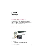
USB Port 1, 2 Connector
R_USB1
Ethernet Connector 8
C N 18
USB Port 3, 4 Connector
CN2
Fan Power Connector 1
FAN1
LED Connector
CN5
Fan Power Connector 2
FAN2
184-Pin DDR Memory Socket 1
DDR1
Fan Power Connector 3
FAN3
184-Pin DDR Memory Socket 2
DDR2
PCI-X 64bit Slot
SLOT1
Socket 478 CPU Socket
SOCKET_1
A TX12V CPU Power
Connector
ATX_12V1
System BIOS
U8
ATX Power Connector
ATX1
Compact Flash Card Slot
CN1
Mini-PCI Connetcor
J 1
Internal Battery
BAT1
Internal Keyboard Connector
CN8
Internal Buzzer
BU1
Internal Mouse Connector
CN9
Serial ATA Connecter 1
S _ATA1
Serial ATA Connecter 2
S_ATA2
Summary of Contents for NA-1531
Page 1: ...FASTORA NA 1531 NA 1801 Hardware Installation Guide For service person only...
Page 6: ...vi...
Page 7: ...Table of Contents vii This page does not contain any information...
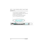
Page 12: ...NA 1531 NA 1801 Networking Application Platform Hardware Installation Guide Introduction 12...
Page 13: ...Table of Contents 13 1 4 Dimensions Unit mm...
Page 15: ...Table of Contents 15...
Page 31: ...Power Supply Specifications 31...
Page 66: ...66 This page does not contain any informati on...


