background image

www.fastech-motions.com - 27

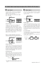
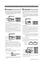
◆ CW, CCW Input

This signal can be used to receive a positioning pulse 

command from a  customer host motion controller. 

The customer can select 1-Pulse Input mode or  2-Pulse

Input mode(refer to switch No.1, SW 1). The input schematic of  

CW, CCW is designed for 5V TTL level. When using 5V level 

as an input signal, the resistor Rx is not used and connect to 

the drive directly. When the level of input signal is more than 

5V, Rx resistor is required. If the resistor is absent, the drive 

will be damaged! If the input signal level is 12V, Rx value is 

680ohm and 24V, Rx value is 1.8Kohm. 

Pulse input signals of the drive are all photocoupler 
protected. The signal shows the status of internal 
photocouplers [ON : Conduction], 
[OFF : Non-conduction], not displaying the voltage 
levels of the signal. 

◆ Alarm Reset Input

Release the alarm output of the drive where the protection 

function is activated. When the Alarm Reset input is set to 

[OFF], the alarm output is canceled. Remove the cause of the 

alarm before releasing the alarm output. If the cause of the 

alarm is not removed, the Alarm Reset input will not operate 

normally even if it is set to [OFF].

※  By setting the alarm reset input signal [ON], cancel the Alarm 

output. Before cancel the Alarm output, have to remove the source 
of alarm. 

◆ Servo On/Off Input

This input can be used only to adjust the position by manually

moving the motor shaft from the load-side. By setting the 

signal [LOW], the drive cuts off the power supply to the motor. 

Then, one can manually adjust output position. When setting 

the signal back to [High], the drive resumes the power to the 

motor and recovers the holding torque. When driving a motor, 

one needs to set the signal [High].

Servo On / Off and Alarm Reset of the drive are
operated with voltage level [ON : High] and [OFF : Low]. 

Alarm and In-Position signals of the drive are operated 
by  [ON : Conduction] and [OFF : Non-conduction] of 
open-drain circuit.

Input Signal

1

Output Signal

2

◆ Alarm Output

The Alarm output indicates [ON] when the drive is in a normal 

operation. If a protection mode has been activated, it goes 

[OFF]. A host controller needs to detect this signal and stop 

sending a motor driving command.  When the drive detects 

an abnormal operation such as overload or over current of 

the motor, it sets the Alarm output to [OFF], flashes the Alarm 

LED, disconnect the power to a motor and stops the motor 

simultaneously. 

◆ In-Position Output

The In-Position output is used to send motor motion to the 

host controller. When the movement of the motor is completed, 

the In-Position output becomes [ON].

In-Position output is [ON] when the motor stops within the 

position deviation set value.

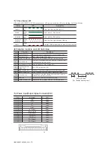
Pin No.

Function

11

CW+

12

CW-

9

CCW+

10

CCW-

※  Please use the input voltage 

   5-24VDC. If the input is not 

   connected, it is in the High state. 

   If the input voltage is less than 

   0.6V, it is the Low state.

Pin No.

Function

7

Servo On/Off

8

Alarm Reset

Pin No.

Function

5

Alarm

6

In-Position

18. Control Signal Input/Output Description [Ezi-SERVOⅡ-BT-28 series]

Summary of Contents for Ezi-Servo II BT

Page 1: ...Operating Manual www fastech motions com ...

Page 2: ...VOⅡ BT 28 series 16 1 Options 16 2 Connector Specifications 17 External Wiring Diagram Ezi SERVOⅡ BT 28 series 18 Control Signal Input Output Description Ezi SERVOⅡ BT 28 series 19 Parameter Settings Ezi SERVOⅡ BT 28 series 20 Specifications of Drive Ezi SERVOⅡ BT 42 56 60 series 21 Settings and Operation Ezi SERVOⅡ BT 42 56 60 series 21 1 Drive status LED 21 2 Pulse Input Setting Switch SW1 21 3 ...

Page 3: ...he manual is damaged or lost please go to the homepage www fastech motions com and downloaded the manual Our company is not responsible for a product breakdown due to user s dismantling for the product and such a breakdown is not guaranteed by the warranty Put the Safety First Before installation operation and repairing the Ezi SERVOⅡ BT thoroughly read the manual and fully understand the contents...

Page 4: ...r Otherwise a fire or other kinds of accidents may occur due to overheating The process of Installation Connection Operation Checking and Repairing should be done with qualified person Otherwise a fire or other kinds of accidents may occur Attention Warning Connect Cables Keep the rated range of lnput Voltage for Ezi SERVOⅡ BT Otherwise a fire or other kinds of accidents may occur Cable connection...

Page 5: ...o Ezi SERVOⅡ BT The machine may get damaged or the user may get injured by motor operation All parameter values are set by default factory setting value Change this value after reading this manual throughly Otherwise the machine may get damaged or other kinds of accidents may occur Stop to supply power to the main circuit and wait for a while before checking or repairing the Ezi SERVOⅡ BT Electric...

Page 6: ...al tuning after the system is installed especially if more that one axis are interdependent Ezi SERVOⅡ employs the best characteristics of stepper closed loop motion controls and algorithms to eliminate the need of tedious gain tuning required for conventional closed loop servo systems This means that Ezi SERVOⅡ is optimized for the application and ready to work right out of the box The Ezi SERVOⅡ...

Page 7: ...OⅡ utilizes the unique characteristics of stepping motors and locks itself into the desired target position eliminating Null Hunt This feature is especially useful in applications such as nanotech manufacturing semiconductor fabrication vision systems and ink jet printing in which system oscillation and vibration could be a problem 7 Smooth and Accurate Ezi SERVOⅡ is a high precision servo drive u...

Page 8: ...sition and automatically recovering to the original position even after experiencing positioning error due to external forces such as mechanical vibration or vertical positional holding 3 Ezi SERVO utilizes 100 of the full range of rated motor torque contrary to a conventional open loop stepping driver that can use up to 50 of the rated motor torque due to the loss of synchronism 4 Capability to o...

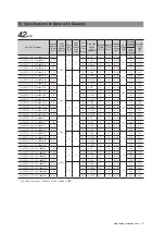
Page 9: ...M B Ezi SERVOⅡ BT 42L A Ezi SERVOⅡ BT 42L B Ezi SERVOⅡ BT 42XL A Ezi SERVOⅡ BT 42XL B Ezi SERVOⅡ BT 56S A Ezi SERVOⅡ BT 56S B Ezi SERVOⅡ BT 56M A Ezi SERVOⅡ BT 56M B Ezi SERVOⅡ BT 56L A Ezi SERVOⅡ BT 56L B Ezi SERVOⅡ BT 60S A Ezi SERVOⅡ BT 60S B Ezi SERVOⅡ BT 60M A Ezi SERVOⅡ BT 60M B Ezi SERVOⅡ BT 60L A Ezi SERVOⅡ BT 60L B Unit Part Number Motor Model Number Drive Model Number Ezi SERVOⅡ BT 42S A...

Page 10: ...ERVOⅡ BT 42XL A PN40 1 40 Ezi SERVOⅡ BT 42XL B PN40 Ezi SERVOⅡ BT 42XL A PN50 1 50 Ezi SERVOⅡ BT 42XL B PN50 Unit Part Number Motor Model Number Drive Model Number Reduction gear ratio Ezi SERVOⅡ BT 56S A PN3 Motor Drive Integrated 1 3 Ezi SERVOⅡ BT 56S B PN3 Ezi SERVOⅡ BT 56S A PN5 1 5 Ezi SERVOⅡ BT 56S B PN5 Ezi SERVOⅡ BT 56S A PN8 1 8 Ezi SERVOⅡ BT 56S B PN8 Ezi SERVOⅡ BT 56S A PN10 1 10 Ezi SE...

Page 11: ...60M A PN25 1 25 Ezi SERVOⅡ BT 60M B PN25 Ezi SERVOⅡ BT 60M A PN40 1 40 Ezi SERVOⅡ BT 60M B PN40 Ezi SERVOⅡ BT 60M A PN50 1 50 Ezi SERVOⅡ BT 60M B PN50 Ezi SERVOⅡ BT 60L A PN3 1 3 Ezi SERVOⅡ BT 60L B PN3 Ezi SERVOⅡ BT 60L A PN5 1 5 Ezi SERVOⅡ BT 60L B PN5 Ezi SERVOⅡ BT 60L A PN8 1 8 Ezi SERVOⅡ BT 60L B PN8 Ezi SERVOⅡ BT 60L A PN10 1 10 Ezi SERVOⅡ BT 60L B PN10 Ezi SERVOⅡ BT 60L A PN15 1 15 Ezi SERV...

Page 12: ...T LOAD N Lower than motor weight INSULATION RESISTANCE Mohm 100 MIN at 500VDC INSULATION CLASS CLASS B 130 OPERATING TEMPERATURE 0 to 55 MODEL Ezi SERVOⅡ BT 56 series Ezi SERVOⅡ BT 60 series UNIT 56S 56M 56L 60S 60M 60L DRIVE METHOD BI POLAR NUMBER OF PHASES 2 2 2 2 2 2 CURRENT per PHASE A 3 0 3 0 3 0 4 0 4 0 4 0 HOLDING TORQUE N m 0 64 1 0 1 5 0 88 1 28 2 4 ROTOR INERTIA g cm2 180 280 520 240 490...

Page 13: ...0 0 08 0 06 0 04 0 02 0 10 500 1 000 1 500 2 000 2 500 3 000 28S 28M 28L 24V Motor Voltage 1 5 1 2 0 9 0 6 0 3 0 10 500 1 000 1 500 2 000 2 500 3 000 24V Torque N m Speed rpm 56S 56M 56L Motor Voltage Ezi SERVOⅡ BT 28 series Ezi SERVOⅡ BT 56 series Ezi SERVOⅡ BT 42 series Ezi SERVOⅡ BT 60 series 1 8 1 5 1 2 0 9 0 6 0 3 0 10 500 1 000 1 500 2 000 2 500 3 000 24V 60S 60M 60L Motor Voltage Speed rpm ...

Page 14: ...1 8 0 2 54 20 0 2 69 5 4 M3 DP4 5 Ø5 0 011 0 Ø4 5 0 1 Ø22 0 05 0 Ø0 075 A 0 1 A 0 025 A 60 0 5 L 33 1 20 6 0 5 4 50 0 25 60 L 1 6 3 0 25 1 6 0 2 54 44 15 0 2 77 4 Ø5 0 THRU 0 3 Ø8 0 013 0 2 7 5 0 1 Ø36 0 039 0 Ø0 075 A 0 1 A 0 025 A 28mm Model name Length L 28S 32 28M 45 28L 50 56mm Model name Length L 56S 46 56M 55 56L 80 42mm Model name Length L 42S 34 42M 40 42L 48 42XL 60 60mm Model name Lengt...

Page 15: ...otor Unit Weight including Motor and Electronic Brake Motor specification and torque characteristic are same as Standard Motor Unit Part Number Motor Model Number Electronic Brake Motor Unit Weight g Permitted Overhung Load N Permitted Thrust Load N Type Voltage Input V Rated Current A Power Consumption W Statical Friction Torque N m Length from Motor Point mm 3 8 13 18 Ezi SERVOⅡ BT 42S BK Motor ...

Page 16: ...63 0 5 L 96 1 5 L 33 1 42 Ø 22 0 02 0 Ø 5 0 015 0 0 075 A 0 025 A 0 1 A SMR 04V N JST Lead wire UL3398 AWG26 Length 400mm 54 4 Ø4 5 THRU P C D 70 7 7 5 15 6 2 19 2 1 5 46 5 L 1 60 44 77 65 7 0 5 L 98 7 1 5 L 33 1 60 Ø 36 0 02 0 Ø 8 0 028 0 012 0 075 A 0 025 A 0 1 A 56mm 42mm 60mm Model Name Length L Weight kg 42S 34 0 58 42M 40 0 65 42L 48 0 72 42XL 60 0 85 Model Name Length L Weight kg 56S 46 1 1...

Page 17: ...Ⅱ BT 42M PN15 4 14 5 7 15 0 0024 6 12 0 200 1 06 410 540 Ezi SERVOⅡ BT 42M PN25 6 90 25 0 00144 9 18 0 120 490 640 Ezi SERVOⅡ BT 42M PN40 9 00 40 0 0009 9 18 0 75 570 640 Ezi SERVOⅡ BT 42M PN50 9 00 50 0 00072 9 18 0 60 620 640 Ezi SERVOⅡ BT 42L PN3 0 93 77x10 7 3 5 3 0 012 6 12 0 1000 1 02 240 270 Ezi SERVOⅡ BT 42L PN5 1 55 5 0 0072 9 18 0 600 290 330 Ezi SERVOⅡ BT 42L PN8 2 48 8 0 0045 9 18 0 37...

Page 18: ...7 2 50 0 00072 27 50 0 60 1100 1100 Ezi SERVOⅡ BT 56M PN3 2 0 280x10 7 3 5 3 0 012 18 35 0 1000 2 15 430 310 Ezi SERVOⅡ BT 56M PN5 3 4 5 0 0072 27 50 0 600 510 390 Ezi SERVOⅡ BT 56M PN8 5 5 8 0 0045 27 50 0 375 600 480 Ezi SERVOⅡ BT 56M PN10 6 9 10 0 0036 18 35 0 300 640 530 Ezi SERVOⅡ BT 56M PN15 10 15 0 0024 18 35 0 200 2 35 740 630 Ezi SERVOⅡ BT 56M PN25 16 7 25 0 00144 27 50 0 120 870 790 Ezi ...

Page 19: ...PN50 24 7 50 0 00072 27 50 0 60 1100 1100 Ezi SERVOⅡ BT 60M PN3 2 6 490x10 7 3 5 3 0 012 18 35 0 1000 2 0 430 310 Ezi SERVOⅡ BT 60M PN5 4 4 5 0 0072 27 50 0 600 510 390 Ezi SERVOⅡ BT 60M PN8 7 0 8 0 0045 27 50 0 375 600 480 Ezi SERVOⅡ BT 60M PN10 8 8 10 0 0036 18 35 0 300 640 530 Ezi SERVOⅡ BT 60M PN15 12 8 15 0 0024 18 35 0 200 2 2 740 630 Ezi SERVOⅡ BT 60M PN25 21 4 25 0 00144 27 50 0 120 870 79...

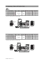
Page 20: ...on will be marked in The code of encoder resolution will be marked in Unit Part Number Motor Stage Reduction Gear Ratio L Length mm Ezi SERVOⅡ BT 42S PN Motor Drive Integrated Single Stage 3 5 8 10 34 Ezi SERVOⅡ BT 42M PN 3 5 8 10 40 Ezi SERVOⅡ BT 42L PN 3 5 8 10 48 Ezi SERVOⅡ BT 42XL PN 3 5 8 10 60 Unit Part Number Motor Stage Reduction Gear Ratio L Length mm Ezi SERVOⅡ BT 42S PN Motor Drive Inte...

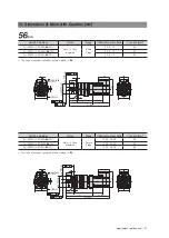
Page 21: ...63 69 5 M5 DP12 5 2 The code of encoder resolution will be marked in The code of encoder resolution will be marked in Unit Part Number Motor Stage Reduction Gear Ratio L Length mm Ezi SERVOⅡ BT 56S PN Motor Drive Integrated Single Stage 3 5 8 10 46 Ezi SERVOⅡ BT 56M PN 3 5 8 10 55 Ezi SERVOⅡ BT 56L PN 3 5 8 10 80 Unit Part Number Motor Stage Reduction Gear Ratio L Length mm Ezi SERVOⅡ BT 56S PN Mo...

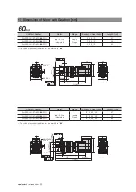
Page 22: ...69 5 M5 DP12 5 2 The code of encoder resolution will be marked in The code of encoder resolution will be marked in Unit Part Number Motor Stage Reduction Gear Ratio L Length mm Ezi SERVOⅡ BT 60S PN Motor Drive Integrated Single Stage 3 5 8 10 47 Ezi SERVOⅡ BT 60M PN 3 5 8 10 56 Ezi SERVOⅡ BT 60L PN 3 5 8 10 85 Unit Part Number Motor Stage Reduction Gear Ratio L Length mm Ezi SERVOⅡ BT 60S PN Motor...

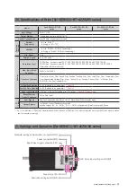
Page 23: ...00kHz Duty 50 Protection Functions Over Current Error Over Speed Error Position Tracking Error Over Load Error Over Temperature Error Motor Connect Error Encoder Connect Error In Position Error ROM Error Position Overflow Error In Position Selection 0 63 Selectable by parameter Default 0 Position Gain Selection 0 63 Selectable by parameter Default 3 Pulse Input Method 1 Pulse 2 Pulse Selectable by...

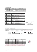
Page 24: ... operation is finished position error more than 1 pulse is continued for more than 3 seconds 12 ROM Error Error occurs in parameter storage device ROM 15 Position Overflow Error Position error value is higher than 180 in motor stop state Alarm LED flash Ex Position tracking error Status LED Description Disable Green Red Green light flashing Red light off Enable Green Red Green light on Red light o...

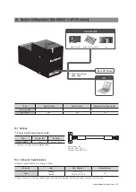
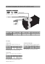
Page 25: ...e Item Length m Remark CSVB A OR4F 0 4m Normal Cable This cable is provide item as standard option Purpose Item Part Number Manufacturer Signal Housing Terminal GHR 12V S SSHL 002T P0 2 JST 16 2 Connector Specifications Connector specifications for cabling to drive Above connector is the most suitable product for the drive applied Another equivalent connector can be used 16 System Configuration Ez...

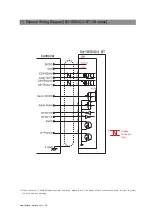
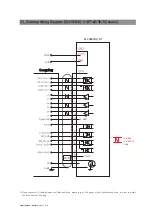
Page 26: ...hielded Twisted Pair Cable When connects I O cable between controller and drive please turn off the power of both controller and drive in order to protect the drive from any damage 17 External Wiring Diagram Ezi SERVOⅡ BT 28 series ...

Page 27: ...from the load side By setting the signal LOW the drive cuts off the power supply to the motor Then one can manually adjust output position When setting the signal back to High the drive resumes the power to the motor and recovers the holding torque When driving a motor one needs to set the signal High Servo On Off and Alarm Reset of the drive are operated with voltage level ON High and OFF Low Ala...

Page 28: ...g this drive setting program user can find the optimal condition to Ezi SERVOⅡ BT to fit with the user s own system Please be noticed that connection for drive setting program shall be done when the Ezi SERVOⅡ BT is disable staus for safety reason Graphic User Interface GUI Program can be downloaded from website www fastech motions com Graphic User Interface GUI Program can support Window 7 8 10 G...

Page 29: ...or Over Temperature Error Over Regenerated Voltage Error Motor Connect Error Encoder Connect Error In Position Error ROM Error Position Overflow Error In Position Selection 0 63 Selectable by parameter Default 0 Position Gain Selection 0 63 Selectable by parameter Default 3 Pulse Input Method 1 Pulse 2 Pulse Selectable with DIP switch Default 2 Pulse Mode Speed Position Control Command Pulse Train...

Page 30: ...0 1 5 3 600 1 500 6 5 000 2 1 000 7 6 400 3 1 600 8 7 200 4 2 000 9 10 000 Protection functions and LED flash times Times Protection Conditions 1 Over Current Error The current through power devices in inverter exceeds the 4 8A 2 Over Speed Error Motor speed exceeds 3 000 rpm 3 Position Tracking Error Position error value is higher than 180 in motor run state 4 Over Load Error The motor is continu...

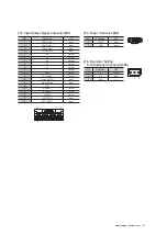
Page 31: ...Output 6 A Output 7 B Output 8 B Output 9 Z Output 10 Z Output 11 Alarm Output 12 In Position Output 13 Servo On Off Input 14 Alarm Reset Input 15 NC 16 BRAKE Output 17 BRAKE Output 18 S GND Output 19 EXT_GND Input 20 EXT_24VDC Input NO Function I O 1 24VDC Input 2 GND Input 2 1 21 6 Parameter Setting Communication Connector CN3 NO Function I O 1 Tx Output 2 Rx Input 3 GND 20 2 19 1 ...

Page 32: ...gth Parameter Setting Cable Cable to connect Ezi SERVOⅡ BT series and computer Please use this cable to change parameter of Drive Item Length m Remark CBTS C F Normal Cable is for Cable Length The unit is 1m and Max 3m length Power Cable Available to connect between Power and Ezi SERVOⅡ BT Item Length m Remark CSVA P F CSVA P M Normal Cable Robot Cable is for Cable Length The unit is 1m and Max 2m...

Page 33: ...gnal CN1 Housing Terminal 501646 2000 501648 1000 AWG 26 28 MOLEX Parameter setting CN3 Housing Terminal 5264 03 5263PBTL MOLEX 22 2 Connector Specifications Connector specifications for cabling to drive Above connector is the most suitable product for the drive applied Another equivalent connector can be used ...

Page 34: ...onnects I O cable between controller and drive please turn off the power of both controller and drive in order to protect the drive from any damage Ⅱ Shielded Twisted Pair Cable 23 External Wiring Diagram Ezi SERVOⅡ BT 42 56 60 series ...

Page 35: ...displaying the voltage levels of the signal In Position Output In Position signal is ON when positioning is completed This signal is ON when the motor position error is within the value set by the Parameter Alarm Output The Alarm output indicates ON when the driver is in a normal operation If a protection mode has been activated it goes OFF A host controller needs to detect this signal and stop se...

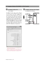
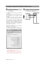
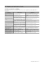
Page 36: ...vel Alarm Output Level Users can use Ezi SERVOⅡ BT according to its own system Please connect parameter setting GUI when Ezi SERVOⅡ BT is Disable state For safety reason Ezi SERVOⅡ BT can not be connected to setting GUI when it is Enable state User Interface Parameter Settings GUI 1 Ezi SERVOⅡ BT 42 56 60 Series Parameter Settings wiring Diagram 2 Graphic User Interface GUI Program can be download...

Page 37: ...haft moves only one direction Pulse Mode of Drive is set as CW CCW input method 2Pulse input method then Controller send Pulse by Pulse Dir method 1Pulse method Please check signal method of Controller Pulse Mode of Drive is set as Pulse Dir input method 1Pulse input method then Controller send Pulse by CW CCW method 2Pulse method Please check signal method of Controller Motor axis moves in the op...

Page 38: ...Checking the assemble status of the unit unscrews debris and deformation structures Fix the defected structure of the equipment Operate motor when brake is locked Checking the brake cable by brake operation sound Checking if 24V is supplied to No 16terminal of I O connector Checking the terminal signal of No 17 of I O connector If brake hold it self it means 24V if not it is 0V Fix the defect of b...

Page 39: ...ng ele ment is near the drive Checking the ambient tempera ture and make sure no heating element near the drive Lower the room ambient temperature to under 25 and do heat dissipation by fan when the temperature of the case is over 50 Remove the heating element from the drive Distance between drive is below 50mm so heat dissi pation is difficult Make sure the distance between drive is more than 50m...

Page 40: ... tension gage After Enable motor does not grab the STEP degree by external force Checking whether mechanical part not moving due to external force Reassemble the mechanical part The wiring of extension cable of motor and encoder is not correct Checking the wiring status of extension cable of motor and encoder Fix the wiring of the cable The motor may have problem Checking the status of the short c...

Page 41: ...www fastech motions com 41 MEMO ...

Page 42: ...www fastech motions com 42 MEMO ...

Page 43: ...www fastech motions com 43 MEMO ...

Page 44: ...or reproduced in whole or in part described in the User s Guide If you need a user manual to the loss or damage etc please contact us or your nearest distributor User manual are subject to change without notice to improve the product or quantitative changes in specifications and user s manual Ezi SERVOⅡ is registered trademark of FASTECH Co Ltd in the national registration ⓒ Copyright 2016 FASTECH...

Reviews: