background image

Set Up Chart Plotter 

31 

Depth Offset 

The Depth Offset setting tells Maestro Navigator how to adjust transducer readings to 
compensate for where the transducer is located on the hull of the vessel. The accuracy 
of your Depth Offset setting affects the accuracy of all depth measurements in Maestro 
Navigator.  Until you specify a Depth Offset, the depth readings indicate the depth from 
wherever the transducer is located on the vessel to the bottom.  


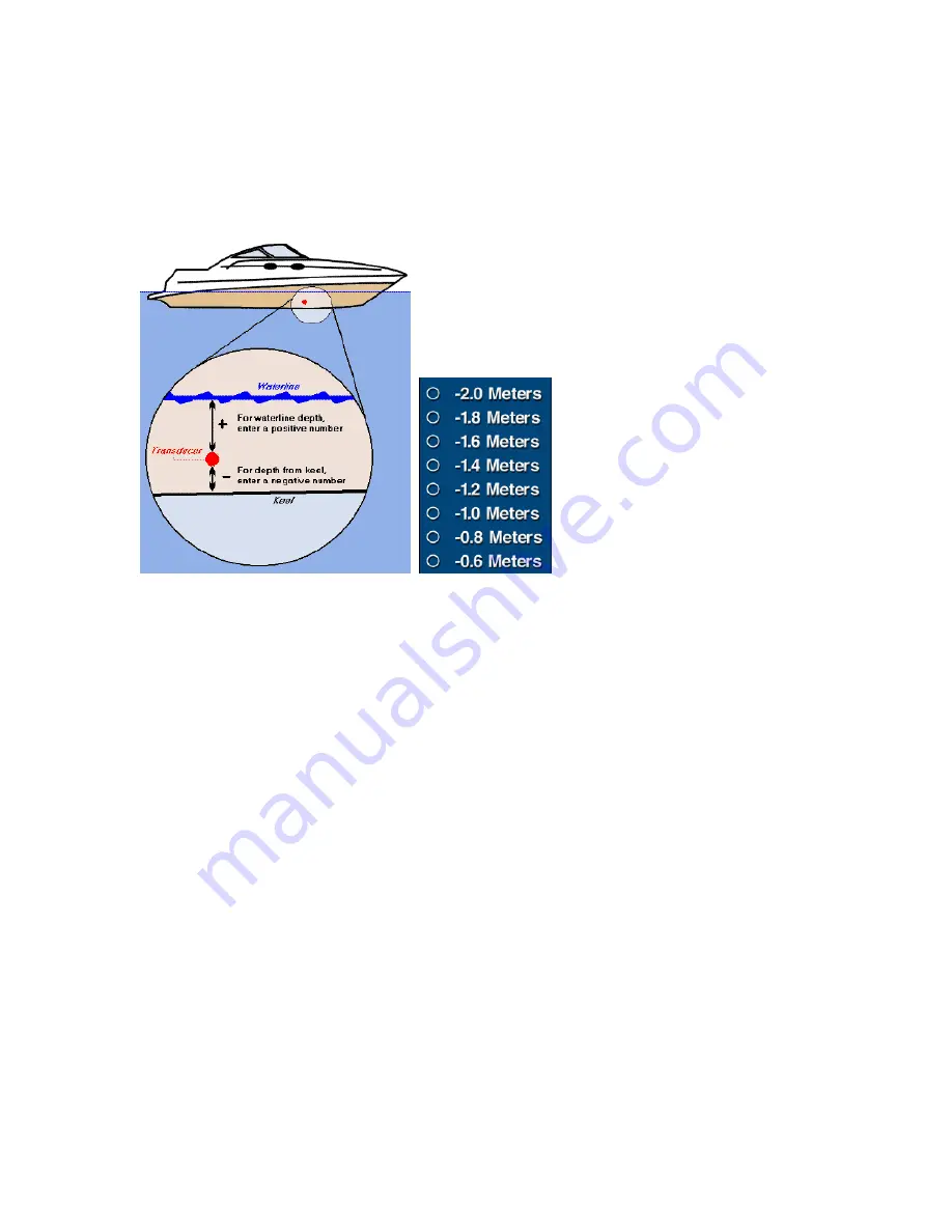
The transducer is mounted somewhere between the keel and the waterline on the hull of 
the vessel. If you would like your depth readings to show depth from another point (such 
as waterline depth, or depth below keel), you must specify a Depth Offset.   
The offset is the distance, in vertical feet, between your transducer and the point from 
which you wish to measure depth. In setting your Depth Offset, you are telling Maestro 
Navigator how to modify the transducer measurement in order to provide the information 
that you want.  For instance, when you want your depth readings to provide the depth 
below keel, specify how far your transducer is above the keel of your vessel.  If your 
transducer is mounted one foot above the keel, enter a Depth Offset of “-1.0.”  This tells 
Maestro Navigator to subtract one foot from the depth reported by your transducer (since 
the keel is one foot closer to the bottom than the transducer is).  As a result, your depth 
readings indicate depth below keel.


To see depth readings that reflect surface depth, and your transducer is mounted two 
feet below your vessel’s waterline, enter “+2.0.”  Maestro Navigator adds two feet to the 
amount reported by the transducer, thereby providing waterline depth. Maestro 
Navigator’s offset range is from -5.0 feet to +5.0 feet, in six-inch increments.  To specify 
your offset, touch 

Setup, Depth Offset,

 and select a value from the available options.   

 
To receive waterline depth measurements, specify a positive number.  For depth from 
keel, specify a negative number.   

Note!   

Depth reading accuracy depends on proper calibration of your transducer’s position in 
the water column.  Refer to your depth sounder user manual to ensure that your system 
is properly calibrated.   

Summary of Contents for Maestro

Page 1: ...User s Manual TM IS0270 rev A ecr 8171 3 2010 ...

Page 2: ......

Page 3: ...ng Lines RBL Setup 34 Manage Routes 37 Day Night Adjustments 38 Chart Colors Adjustments 39 Scroll Speed Setup 40 Manage Tracks 40 Unit Display Formats 41 Upgrade CD DVD 43 Vessel Information 43 Waypoints Set Alarms 44 Zoom Buttons 44 Charts 47 View Charts 47 Marine Facilities 50 Traversing the Charts 51 Linking 54 Find Specific Locations 54 Marks 55 Managing Waypoints 56 Contour Charts 59 Split S...

Page 4: ...nd GPS Options 104 Radar 107 Radar Safety 107 Configure the Radar Display 108 Radar Setup Submenu 114 Sonar Fish Finder 119 Customize Sonar Panel 121 Working with Targets 123 Sonar History 124 Sonar Data on Contour Charts 127 Sonar Related Depth Setup Options 130 Cameras 137 Troubleshooting 139 Troubleshooting General 139 Troubleshooting GPS 140 Troubleshooting Radar 140 Troubleshooting Depth 141 ...

Page 5: ...Maestro Navigator s touch screen brings a new level of convenience to navigating your vessel With a touch screen you use your fingertip to move the cursor instead of dragging it with a mouse Instead of clicking on buttons and menus you touch them directly on the screen x Press or Touch means you should tap the screen with your finger This is equivalent to clicking with the left mouse button on a d...

Page 6: ...ete the close out and save procedures before shutting down it just ends processes wherever there are The NavPanel Once the navigation computer is powered up the NavPanel is displayed on the screen The NavPanel acts as your onboard computer s desktop and provides access to all features information and options for configuring how the system looks and operates The six large buttons in the center of t...

Page 7: ...ust bright enough for nighttime use Screen Ctrl Screen Control Touch here to adjust the brightness and contrast of Maestro Navigator s touch screen may not be available on all models Conn Mgr Touch this button to configure your internet connection settings Shut Off Turns off the navigation computer If you have a dual station network the NavPanel displays two buttons in addition to the ones describ...

Page 8: ......

Page 9: ...ly available when there is no active Route x Route Access to details and functions for the active Route The Route option is only available when there is an active Route x Tools Access to the various Maestro Navigator tools and features such as Mark Distance and Tracking tools x Setup Access to the tools for customizing Maestro display screens Details are described in the Setup Chart Plotter sectio...

Page 10: ...charts contour charts topographic maps of coastal areas and navigation photos available in selected coastal areas Use the Mode button to switch between these different types of charts Nautical Chart Nautical Chart is the default mode used to display charts In the chart list Nautical Charts are indicated with a blue icon ...

Page 11: ...vigation Photo menu option is displayed with darkened print and cannot be selected as pictured above In the chart list Navigation Photo Charts are indicated with a camera icon Topo Map Some of Faria s digital chart packages include USGS topographic maps covering up to five miles inshore from coastal areas If you have installed these Topo Maps you can use them to get a more detailed look at coastal...

Page 12: ...hanges the chart you are currently viewing to a Contour Chart for your location To view contour coverage for an area that does NOT contain your vessel location you must first open a nautical chart for the desired area then switch to Contour Chart coverage Touch View Chart and select a nautical chart title When the map is displayed then touch Mode Contour Chart to switch to and see a contour chart ...

Page 13: ...rine Facilities you can change the display sorting order Select a name to refresh the screen and view the chart where the facility is located Touch the mark on the chart to see a pop up display of facility information x Tide Station Displays a list of available Tide Station Charts you can change the sorting order Select the name then touch Station Information to view that graph x Current Station D...

Page 14: ...or 3 5 3 doc 10 Go To Menu For detailed information on how to use the Go To menu options refer to the Plotting and Storing Routes section of this Manual The Go To option is not available when there is an active Route ...

Page 15: ...oute is not locked you can use your finger to drag Waypoints to locations on the chart Text label changes to Unlock Route x Deactivate Route Tells Navigator that you are abandoning this route x Reverse Direction For returning to the beginning of the route reverses the sequence of Waypoints x Rename Active Route When you create a route it is automatically assigned a name consisting of the date and ...

Page 16: ...h the chart location where you would like to place the new Waypoint When you touch any area outside the route the new Waypoint is attached to the end of the route before after To insert the new Waypoint between other Waypoints within the route touch the route line at the new location before after Remember you can move Waypoints by touching and dragging them to the new location ...

Page 17: ...you want to take another look at updated data Tools Menu This is a quick overview on what options are available in the Tools Menu For detailed information on how to further use the options available for each Tool refer to the Charts or Plot and Store Routes sections of this manual x Mark Tool Create and Name preset locations on charts x Drag Pan Tool Default tool touch and drag your finger to move...

Page 18: ...ename or delete existing Marks set course for a Mark and create new Marks x Overlays Show or Hide icons on the chart Photo Tide Current x Range Rings Set the distance between the Range Rings that are drawn around the vessel to help gauge distance x Range Bearing Lines A Range Bearing Line RBL is a straight line between your vessel and another point on the chart x Routes Displays a list of all Rout...

Page 19: ...rent stations throughout the area x Coast Pilot Published by NOAA as a supplement to nautical charts Coast Pilot contains channel descriptions bridge and cable clearances ice conditions traffic separation schemes and other information not found on the printed charts x Light List Descriptions and locations of lights buoys etc x Chart Symbols A key to the symbols and abbreviations commonly used on N...

Page 20: ...r a closer view or move back to see a larger area of the Chart Each press of the plus button zooms in closer by a factor of approximately 50 roughly twice as close Press the minus button to move farther out from the chart also by a factor of approximately 50 to see more area on the screen In each case the point at the center of the screen remains the same Limit of Plus button For areas where you d...

Page 21: ...sel Lat Lon The latitude and longitude of your present position x Vessel SOG COG Speed Over Ground and Course Over Ground x Vessel SMG CMG Speed Made Good and Course Made Good x Cursor Lat Lon The latitude and longitude of the cursor changes as you move around the chart x Cursor Rng Brng Range and bearing from the vessel to the cursor position x Waypoint Rng Brng Range and bearing from the vessel ...

Page 22: ...gs and charted position Further explanation of these options is listed below Vessel Lat Lon Select the Vessel Lat Lon option to change the data window and display Vessel Coordinates as pictured below Vessel SMG CMG Select the Vessel SMG CMG option to change the data window and display speed made good using the selected units of measure and course made good indicating True or Magnetic North as pict...

Page 23: ...to the right indicating that the next Waypoint is starboard After steering to the right and once the vessel is aimed in the direction of the next Waypoint the arrow points straight up This is Chart Up chart orientation The Chart remains the same and the vessel icon rotates to stay on course Chart Up orientation is especially handy when you re using the Waypoint Pointer because straight up for the ...

Page 24: ...h Warning in action When the Data Window is set to display the Look Ahead graphic you can see the upcoming impact zone represented by the red in the cross section display If you want to monitor depth changes as you cruise and you re planning to keep an eye on the screen as you go the Look Ahead option is a handy reference If you aren t concerned about minor depth changes but you want something to ...

Page 25: ...des currents or depth sounding datum x In anticipating relative depths along your upcoming course the Depth Warning window uses charted depth data from Contour Charts Therefore use of the depth warning requires the presence of contour coverage Look Ahead Data Window The Look Ahead data window shows a one mile cross section of your vessel s present course and uses different colors to indicate areas...

Page 26: ... x The Look Ahead window is intended for use as a navigational aid and should not be solely relied upon for safety during navigation Even when the Look Ahead window shows white indicating that no obstructions are detected obstructions may still be present x The depth alarm setting which is used by the Look Ahead data window is not corrected for the effects of tides currents or depth sounding datum...

Page 27: ... so you can install the charts on your home computer for use with the Home Planning Edition This way in the unlikely event that charts are deleted from your navigation computer you can also use the CD DVD to restore them Maestro Navigator recognizes Maptech NOAA BSB format Nautical Charts Faria Coastal Navigation Photos Faria Coastal Topographic Maps Faria Aerial Pictures and Faria Contour 3D Char...

Page 28: ...spinning and the Copy Charts window closes Note Product registration required Nautical Charts and Contour 3D Charts must be unlocked before they can be used Unlocking requires a special code obtained during product registration To register your chart product s and unlock your nautical contour charts contact Faria registration at 877 405 1010 One registration per chart region includes both nautical...

Page 29: ...uctions and adjusting the Depth Line Contour Colors Contour charts can be shown using several different color schemes so you can select the one that s easiest to see under the current lighting conditions 2007 NSI inc Press Setup Contour Colors and choose from the following list x Deep Blue Blue tones are used this is the original factory default setting x Rainbow Red Green Yellow tones are used to...

Page 30: ...ll find options to Show or Hide Contour Obstructions Depth Staff Display The Depth Staff is an optional visual aid designed to help you gauge depth at a glance 2007 NSI inc The Depth Staff is a purple line extending directly downward from the vessel icon on a Contour Chart Charted depth is noted at intervals along the staff To turn the Depth Staff on or off touch Setup Contour Depth Staff Display ...

Page 31: ...how or hide the Transducer Cone touch Setup Contour Transducer Cone Note Turning the Transducer Cone graphic off and on has no effect on whether your actual transducer is on or off Depth Line The Depth Line is an optional visual aid on the Contour Chart display window It is a light shaded plane that appears to float directly beneath the vessel icon 2007 NSI inc To turn the Depth Line on and off to...

Page 32: ... in the Sonar control panel Surface Layer The Surface Layer is a visual aid that represents the surface of the water 2007 NSI inc The Surface Layer options add a flat graph pattern to the Contour Chart representing the water s surface The squares in the grid measure 50 meters on each side The Surface Layer menu has the following options x Surface Layer The standard surface layer shown in the image...

Page 33: ...cally displayed in green It turns red when the Depth Alarm is triggered or if the Look Ahead data window indicates a collision based on present heading Area Display The Area Display is a notation on the contour chart indicating the rough dimensions of the Contour Chart that is currently being displayed Pictured below under East 2007 NSI inc Touch Setup Contour Area Display to turn the Area Display...

Page 34: ...Alarm Set the alarm to the depth at which you want to be notified When your vessel is equipped with a depth transducer or Fishfinder Maestro Navigator sounds a beep and displays a message window when your vessel attains the depth indicated in the Depth Alarm To close the message window press Acknowledge Depth Alarm Tips In setting the Depth Alarm consider your vessel s draft when fully laden and s...

Page 35: ...instance when you want your depth readings to provide the depth below keel specify how far your transducer is above the keel of your vessel If your transducer is mounted one foot above the keel enter a Depth Offset of 1 0 This tells Maestro Navigator to subtract one foot from the depth reported by your transducer since the keel is one foot closer to the bottom than the transducer is As a result yo...

Page 36: ...rmance in some circumstances To specify Display Quality touch Setup Display Quality then choose Low or High Click on Cancel to close the tool without changing the setting Manage Marks Marks are user defined locations on a chart You can modify existing Marks delete the ones you no longer need set course for a Mark or create a new Mark by pressing Setup Marks When there are stored Marks in the syste...

Page 37: ... x Hide mark Hides the selected Mark from view Although the Mark is removed from the display it remains in the list of Marks Once a Mark is hidden you can make it visible again by selecting it and choosing Show mark x Lock mark Prevents the Mark from being moved on the charts x Unlock mark Unlocks a previously locked Mark When Marks are unlocked they can be moved by dragging with your finger on th...

Page 38: ...ring Line RBL is a straight line between your vessel and another point on the chart The endpoint is labeled with the range distance and bearing from the vessel to the line s end point You can create RBLs between your vessel and any location To view a list of all your RBLs and make modifications touch Setup Range Bearing Lines You can modify any RBL in this list Use the up and down arrows to scroll...

Page 39: ...ange Bearing Line x Lock Range Bearing Line Prevents the end point of the highlighted RBL from be accidentally moved x Unlock Range Bearing Line Unlocks a locked RBL so the end point can be moved freely x Close Closes the RBL menu and centers the display on the vessel location New Range Bearing Line Select the New Range Bearing Line option and a key pad tool pops up on the screen enter the coordin...

Page 40: ...orm the actions described below x Set Range Bearing Line Location Enter the new coordinates of the end point using the pop up keypad x Delete Range Bearing Line Permanently deletes the selected RBL x Lock or Unlock Range Bearing Line Locks or unlocks the selected RBL A locked RBL cannot be moved x Hide Range Bearing Line Hides the selected RBL from view Although the RBL hidden it remains in the li...

Page 41: ...tion to the starting point of the Route Note It is up to you to verify that the course is charted in safe waters x Go to reverse route Sets course for the highlighted route but in reverse starting at the ending Waypoint x Rename route Change the name of the selected Route using the on screen keyboard x Delete route Permanently remove the selected Route from memory x Lock route Lock all the Waypoin...

Page 42: ...urately reproduces the colors found on printed charts Night has a darker color scheme to help preserve your night vision Touch Setup Day Night and choose from the following options Day The default setting displays in the original chart colors Night A darker color palette based on shades of gray and red By keeping the display just bright enough for nighttime use your eyes don t have to adjust betwe...

Page 43: ...n high contrast colors improving the readability of charts in certain lighting conditions Touch Setup Chart Colors and one of the following two options Normal Choose Normal to view charts in the normal color display High Contrast Select High Contrast to view charts in high contrast colors ...

Page 44: ...l chart movement When Scrolling is disabled the scrolling arrows won t appear at all Use the Drag Tool pictured below to adjust your view Manage Tracks Routes are user defined courses plotted out on a chart The top half of the window lists all of your existing Routes by Name An asterisk is displayed next to the active Route the Route that your vessel is currently following The Locked column indica...

Page 45: ...played on the screen press OK to use the same name as the Track or type a different name for the Route before pressing OK Maestro Navigator then displays a message telling you how many Track Points were in the Track and how many Waypoints are in the new Route The message also notes the measure of cross track error how closely the new Route follows the original Track line Refer to the Recording Tra...

Page 46: ...when using Magnetic North as a reference Lat Long Coordinate Formats Indicate the format to use when displaying Latitude and Longitude Coordinates Touch Setup Units Coordinates and select one of the following display formats 000º 00 00 DMS Degrees Minutes Seconds 000º 00 00 DMM Degrees Decimal Minutes 000 000000º DD Decimal Degrees Distance Speed Measurements Indicate the type of measurement to us...

Page 47: ...de discs are usually self running but in case the installation program does not start immediately use this menu option to begin the upgrade manually Insert the upgrade disc in the CD drive and touch Setup Upgrade You won t need this menu option unless you need to apply a software upgrade manually Vessel Information Make changes to the Vessel or Owner s Name that is displayed on the various screens...

Page 48: ...ed at or achieved each Waypoint Touch Setup Waypoints Arrival Alarm to tell Maestro Navigator how close the vessel must come to the Waypoint before the alarm is triggered Set the alarm to sound at a certain distance from the Waypoint or at a certain time interval based on the vessel s current speed Example Set the arrival alarm to 100 feet and when your vessel comes within 100 feet of the Waypoint...

Page 49: ...and Scale When set to Zoom and Scale the plus and minus buttons adjust the view by changing the zoom level on the current chart or switch to another chart at a different scale In deciding whether to change zoom level or chart scale Maestro Navigator takes two things into account the zoom level at which you are viewing the current chart and the availability of other charts for the area For example ...

Page 50: ......

Page 51: ...ur position make sure the plus and minus buttons are set to Zoom and Scale Refer to the Setup Zoom Buttons section of this manual for more details The following sections explain the various Chart options offered by Maestro Navigator View Charts Once copied onto the hard drive all of the Charts are always available for use If your pre installed chart data needs to be reinstalled for any reason foll...

Page 52: ...e chart title to open it on the screen Once the Chart is displayed press the plus button to zoom in until you find a comfortable chart scale zoom level Press the minus button to move back out to a wider view Chart Type The following icons are a visual clue to indicate the type of chart this is going to display Nautical charts Topographic maps Navigation photos Switch Chart Display In addition to n...

Page 53: ...n another direction In such cases the chart image is rotated as necessary to achieve north up orientation x Course Up The chart rotates as necessary so that the vessel always points and or moves towards the top of the screen Aerial Pictures As you view your charts you may occasionally come across small blue camera symbols These are picture icons Each picture icon is a link to an aerial picture of ...

Page 54: ...in alphabetical order by their name x Sort by distance to vessel lists the closest facilities first x Sort by distance to screen center lists facilities nearest to the chart area you re viewing which is handy if you re plotting a route and looking for a good place to stop along the way When you find a facility you are interested in touch the name to select it and highlight it in green Touch one of...

Page 55: ...enables you to drag the chart across the screen to view sections that may be obscured from view This cursor tool symbolized by the familiar hand icon lets you drag the chart to reposition the image To activate the Drag Pan tool press the Tools button and choose Drag Pan Tool This tool is selected by default each time you start Maestro Navigator Scrolling The Scrolling tool slowly changing the disp...

Page 56: ...Overview The light green rectangle in the overview indicates what part of the chart you see in the main window As you drag and pan the chart image the green rectangle also moves so that it always indicates the area that you are viewing on the screen You can use the overview to jump to another portion of the chart quickly Touch another part of the chart in the thumbnail view window to display that ...

Page 57: ...scrolling across a large area in search of a particular point try switching scales You can scale out for a wider view of the area center the screen on your point of interest and scale in again to a detailed chart of the area at the center of your screen Chart Information When viewing a nautical chart the third button along the bottom of the Maestro Navigator window displays the chart s units of de...

Page 58: ...hart After you stop scrolling the chart Maestro Navigator will wait 12 seconds so that you can look around before automatically returning to your vessel location The 12 seconds are counted down for you and displayed on the Link button so that you know when to expect your vessel location to reappear on the screen Keep Vessel in Sight Press the Link button at the bottom of the screen and select a li...

Page 59: ...as a small purple circle labeled M with an identifying name label Marking a Chart Follow the steps outlined below to create Marks 1 Open the chart to the location where you want to create the Mark 2 Press the Tools button and choose Mark Tool 3 A blue outline box is displayed with arrows on each of the four sides and in each corner 4 Use the blue arrows to navigate the box so the area you would li...

Page 60: ...h the Mark on the chart and a pop up menu is displayed Choose View Mark at Max Scale to open the most detailed chart available for the mark s location Edit Marks Touching a Mark opens a pop up menu with various options You can delete the Mark or add it to the route you re following You can change its location by assigning a new latitude and longitude choose Set Mark Location or by dragging it to a...

Page 61: ...are represented by purple W symbols and are joined by blue lines called route legs Other colors are used to indicate specific Waypoints and route legs The S in a green circle indicates the vessel location at the beginning of the active route The green line of the route indicates the first leg of the route from start to first Waypoint The active Waypoint is where you are headed next indicated with ...

Page 62: ...esented by a yellow symbol and the route leg leading to it is highlighted in purple Once you arrive at the active Waypoint the next Waypoint in the sequence becomes the Active Waypoint Change Active Waypoint As you re following a route you may decide to skip ahead and omit some Waypoints along the way or you might decide to backtrack to a previous Waypoint You need to tell Maestro Navigator about ...

Page 63: ...l icon positioned above the terrain atop a vertical line indicating the water depth To view your vessel location on a Contour Chart touch Mode Contour This changes the display of the current chart to the Contour Chart for your vessel s location To view contour coverage for an area that does NOT contain your vessel location you must first open a Nautical Chart for the desired area then switch to co...

Page 64: ...t side of the screen You can continue to rotate the vessel in this way to a full 360 degrees The example above shows the view forward then rotated to show the view aft You can also raise or lower your viewpoint by moving your finger up or down on the screen Over the Shoulder View Tap the vessel and it will automatically rotate itself so that it points towards the position of 11 o clock ...

Page 65: ...usly in split screen Press Mode Split With and choose the type of chart you d like to split the screen with Both charts are displayed side by side To return to single chart mode touch Mode again and select the chart type you want Dominant Chart When viewing two chart types in split screen mode you ll find that one chart window is dominant If you move the chart in the dominant window the other wind...

Page 66: ...tical chart both indicate the same geographic location Blue Box Cross hairs The Blue Box and Cross hairs indicate the area of the Nautical Chart that is being displayed in the Contour Chart window If the charts are not centered on the vessel that is if you have panned away from your vessel location the cross hair symbol marks the center point of the Contour Chart coverage Note Depending on the cha...

Page 67: ...adjust the contour window s zoom level touch Mode Contour to temporarily show just the contour chart then use the plus and minus buttons to make your adjustments and press Mode Split With Nautical to return to split screen Dragging and Scrolling To view a different area drag your finger across the Nautical Chart Both charts will pan in the direction you re dragging To move the charts faster hold y...

Page 68: ......

Page 69: ... cursor changes to an arrow anchor symbol when creating a route as pictured here 1 Touch the chart at the locations where you would like to place your Waypoints in the order of travel 2 Each Waypoint is marked by a symbol on the chart 3 To move a Waypoint touch it and drag it to the new location 4 To delete a Waypoint press it until a menu pops up then choose Delete Waypoint 5 When you have finish...

Page 70: ...ng a Route When you reach the last Waypoint in your route the Route is deactivated and removed from view Any route related data windows like the Waypoint pointer cross track error time to Waypoint etc are cleared since that data is no longer necessary or relevant However if you decide to stop following a route before you reach its final Waypoint you need to tell Maestro Navigator To do this touch ...

Page 71: ...fies you that the route is completed and the Instant Waypoint symbol disappears Caution A route to an Instant Waypoint is a straight line between your vessel and your destination It is up to you to make sure that your route is charted in safe waters Be sure to view the entire path of your route at the appropriate scale before setting course to make sure the route does not cross through shallow or ...

Page 72: ...ither direction Following a route in reverse lets you retrace your steps To reverse direction of the route you are currently following press Route Reverse Direction Maestro Navigator reverses the order the Route s Waypoints so you can begin at the ending Waypoint and return to the starting Waypoint When you are not currently following a route there is no active Route press Go To choose Stored Rout...

Page 73: ... for it Back Track When you have recorded a Track of your vessel s progress you can turn your vessel around and navigate back along any path you have traveled with the Navigator Back Track feature Maestro Navigator creates a new Route based on the active Track line in reverse so that you can retrace your path to the beginning of the Track This feature is only available when there is no active Rout...

Page 74: ... Marks can be used to navigate To set course for a Mark touch Go To Stored Waypoint Mark and select the desired Mark If the Mark is visible on the screen touch the Mark and choose Go To Mark When you re following a route you can add a Mark to the end of the route touch the Mark and choose Add to Route Marks on Contour Chart Although Marks must always be created on a Nautical Chart they can be view...

Page 75: ... mark x To bring a Mark into view touch View Waypoint Mark and select the Mark from the list A 3D version of the Waypoint or Mark symbol is used for contour charts Managing Waypoints While you re adding Waypoints the cursor is in route mode so you can no longer touch and drag the chart as usual Instead a blue outline box appears on the chart You can place Waypoints anywhere inside the box To move ...

Page 76: ...lled route legs Other colors are used to indicate specific Waypoints and route legs The S in a green circle indicates the vessel location at the beginning of the active route The green line of the route indicates the first leg of the route from start to first Waypoint The active Waypoint is where you are headed next indicated with a yellow W The pink line of the route indicates the leg that leads ...

Page 77: ...nted by a yellow symbol and the route leg leading to it is highlighted in purple Once you arrive at the active Waypoint the next Waypoint in the sequence becomes the Active Waypoint Change Active Waypoint As you re following a route you may decide to skip ahead and omit some Waypoints along the way or you might decide to backtrack to a previous Waypoint You need to tell Maestro Navigator about you...

Page 78: ...urse shown on the autopilot display is safe to follow press the Track button Follow the instructions on the Autopilot screen The Autopilot makes continual adjustments to keep you on course As you follow your Route you must verify that each segment of the Route is safe for navigation The Autopilot sounds an arrival alarm as you reach each Waypoint When you have verified the next leg of the route pr...

Page 79: ...te Touch Route Add New Waypoint and then touch the route line in the places where you d like to add Waypoints 5 Follow Along the Length of the Route Use the chart scrolling feature to move along the route line and continue adding Waypoints Move the cursor to the edge of the screen and hold your finger down to scroll along the length of your route A blue line indicates the scrolling area Touch outs...

Page 80: ...Rename Active Route If you don t want to follow the route right now but you want to save it for future use touch Route Deactivate Route You can follow your route later by touching Go To Stored Route and picking this route out of the list Recording Tracks Maestro Navigator can record the path you travel while you cruise This path of your progress is shown as an orange Track line on the screen The T...

Page 81: ...k Points Every five seconds Maestro Navigator puts down a small cross or X mark on the track line Each cross is referred to as a Track Point The faster your speed the farther apart the track points are placed When you look back at a Track you can see where your speed was faster Track Points are farther apart or slower Track Points are closer together Convert Track to Route Any Track can be convert...

Page 82: ...igator creates a new Route based on the active Track line in reverse so that you can retrace your path to the beginning of the Track This feature is only available when there is no active Route so deactivate the current Route Touch Go To Back Track and a message telling you how many Track Points were in the active track and how many Waypoints are in the new route The message also notes the measure...

Page 83: ...to create an RBL Touch Tools Range Bearing Line Tool The default starting point for an RBL is the center of your vessel Touch the location on the chart where you would like the RBL to end Once the RBL tool is activated you have 12 seconds to create an RBL Before the RBL tool is deactivated A keyboard panel is displayed on the screen You may choose to keep the default name which is the date and tim...

Page 84: ...ange Bearing Line touching the name of the RBL you wish to delete and choosing Delete Both of these options permanently remove the selected RBL from the screen and from memory Viewing an RBL To select an RBL to view touch View Range Bearing Line Select the RBL you wish to view from the list and touch OK The RBL is displayed on the screen centered on its end point Note When viewing an RBL while the...

Page 85: ...extend the line The line and the data readings remain in view as long as you are touching the screen they disappear when you lift your finger You ll notice that when you select the distance tool you can no longer drag the chart image Instead you can scroll the chart press and hold your finger outside the blue box to scroll the chart in the direction of the blue arrows To extend the distance line b...

Page 86: ...Maestro Navigator 3 5 3 doc 82 ...

Page 87: ...level low high or mid tide Different colors and symbols are used to convey this information The tide icon s appearance changes as tidal conditions change Blue Arrow Tide is Rising Red Arrow Tide is Ebbing A blue arrow pointing up indicates that the tide is rising A red arrow pointing down means that the tide is ebbing The wave symbol moves up and down the icon to portray general water level Touch ...

Page 88: ...esent conditions All 24 hours for today s date are shown and a vertical dotted line indicates the present time For Researching Past and Future Conditions use the buttons labeled 1 Day 6 hrs 1 Day 6 hrs to scroll the graph backward and forward in time As you change the day or hour the graph scrolls to represent conditions at the specified time The date and time represented by the dotted vertical li...

Page 89: ...ions are displayed in this list x Sort by name displays the list of Tide Stations in alphabetical order by their name x Sort by distance to vessel lists the closest Tide Stations first x Sort by distance to screen center lists Tide Stations nearest to the chart area you re viewing Touch the name of the Tide Stations to select it and highlight it in green Touch Station Information to display Tide G...

Page 90: ......

Page 91: ...elow illustrates the different phases of the current icon The icons change in appearance over the course of the day to reflect the present conditions at that current station The arrow symbol points in the general direction of the current Note that as the speed increases the arrow symbol becomes filled with color A completely filled arrow represents that the current is moving at or near maximum spe...

Page 92: ... line through the center of the graph indicates a speed of 0 knots slack water x Where the line peaks above the center line blue shading the current is flooding x The valleys red shading between the peaks show when the current is ebbing Historical Currents When you first open the Current Graph it shows the present conditions All 24 hours for today s date are shown and a vertical dotted line indica...

Page 93: ...ist of all Current Stations installed on the system is displayed Use the arrows to scroll through the list Touch one of the sorting options to change the order in which the Current Stations are displayed in this list x Sort by name displays the list of Current Stations in alphabetical order by their name x Sort by distance to vessel lists the closest Current Stations first x Sort by distance to sc...

Page 94: ...Maestro Navigator 3 5 3 doc 90 ...

Page 95: ...X service packages offer a selection of data sources designed to meet a broad or specialized weather monitoring need at affordable prices Activation of an XM WX subscription is easily achieved by calling the XM WX Listener Care at 1 800 985 9200 and selecting option number two for activation Be sure to mention the specific XM WX service package by name There are three data packages available Fishe...

Page 96: ...vation process Advise the XM Listener Care Representative that you are activating an XM WX Satellite Weather Ready Receiver and provide the 8 digit radio ID located on the bottom of the radio on the outside of the packing box or in the XM Link window The Listener Care Representative will ask for billing information and discuss the types of weather data packages that are available for subscription ...

Page 97: ...cle below the logo Touch the dot the left half of the logo or the XmLink button to monitor radio status and view the event log Enable full screen mode by touching the right half of the WxWorx on Water logo Close Reception Status When you are finished viewing the XmLink window minimize it by touching the underscore button in the upper right corner of the menu Do not close the menu by touching the C...

Page 98: ...ht arrow to move it to the right field Select all of the counties in a state at once by touching the Set All button above the field To stop all county notifications touch the Del All button and touch the right arrow Set all the counties in the United States to display warnings by touching the Include All Counties in the U S button Touch the Remove All Counties in the U S button to stop all notific...

Page 99: ...rag diagonally down across the map to draw a box This box shows the boundaries of the area to be zoomed When you lift your finger the screen zooms in refreshing the display with a larger visual of the area in the box Resetting the Map Position The Reset button moves the map view so it is centered on the entire United States The Reset button also moves all displayed data and causes SCIT markers to ...

Page 100: ...the Radar button to display radar reflectivity This display is composed of a composite of all the active NWS radars across the United States It provides 2Km resolution of radar data beginning with 10 DbZ reflectivity and then increasing to 75DbZ The accompanying legend can be used to judge the reflectivity in an area ...

Page 101: ... Options Legends Standard Legend Legend Rain Modes Radar Legend w Snow to add these options to the legend Animate Display The Loop button will animate radar and satellite data To set the number of frames to be looped touch Setup Loop The display can lay the radar data over the satellite data but only one set of data can be looped at a time If you touch the Loop button while both are displayed the ...

Page 102: ...ure for that color shade Temperatures are in Fahrenheit or Celsius Touch Setup Units to change the units of measurement Waves Touch the Waves button to display the height period and direction of ocean waves Data is displayed for one coastal area East or West at a time Touch Options East Coast Waves or West Coast Waves to select the East or West Coast If the Waves button is active when you select a...

Page 103: ...detect any storms If a storm is detected it will appear as a series of icons showing its observed position and continuing with its forecasted positions Touch one of the icons to see details about the storm s behavior at the time that the observation or forecast was made This information includes the storm s latitude and longitude surface pressure average wind speed with gusts in parentheses and mo...

Page 104: ...includes the time at which the observation was made temperature dew point visibility wind direction and speed speed of wind gusts barometric pressure precipitation type and cloud status Buoys are indicated by red and white squares along coastal areas and some inland waters Touch a square to see detailed information about the weather observed at that buoy The data may include the buoy number the ti...

Page 105: ... button flashes orange The warnings are displayed on the map as small colored boxes Light gray boxes indicate flood warnings Blue boxes indicate flash flood warnings Yellow boxes indicate thunderstorm warnings Red boxes indicate tornado warnings Touch Options Legends Warnings Legend to see examples of each warning If you have purchased the optional mapping upgrade the counties affected by warnings...

Page 106: ...displayed will only show infrared satellite information at or above the displayed elevation in increments of 5 000 feet up to 40 000 feet Touch the down arrow to lower the minimum height down to 5000 feet Marine Zone Forecasts Touch the Marine Zones button to display marine forecasts These include the Special Marine Warnings Marine Weather Statements Coastal Waters Forecasts Great Lakes Forecasts ...

Page 107: ...orm markers which have orange outlines and Severe Storm markers which have pink outlines Shear SCIT markers are generated when high wind shear is detected This is identified when inbound and outbound winds are located directly next to each other and exceed a threshold of 50 knots Severe Storm SCIT markers are generated based on the presence of several factors including maximum rain rate hail prese...

Page 108: ...s Determine at what range various communities appear on the map when you touch the Mapping button You can also use the Places Database to add or delete community names from the database To customize your database you must plug the USB keyboard included in your owner s kit into Maestro Navigator s dash The following steps describe how to customize your database 1 Touch Setup Places Database to open...

Page 109: ...ed adding or editing places touch OK to approve the changes and return to the Place List or touch Cancel to discard the changes 5 Repeat steps 3 through 5 to add or edit other places in the selected state 6 Touch the Save button to save changes 7 Touch the Done button to close the Place List Follow this process again to add or edit places in another state While your Places database contains thousa...

Page 110: ... give the color for the rings A value of 255 in all three boxes results in purely white rings while a value of 0 in all three boxes results in purely black rings Percentage of mapping behind vehicle Controls where the vessel icon will appear on the map At 50 the vessel icon will remain in the center of the map while at 40 you will have 40 of the mapping will be behind the boat and 60 forward This ...

Page 111: ...ort Radar If you desire to add the optional Radar feature to your system Faria s technical support staff will be happy to help Contact our staff by telephone fax or e mail Monday through Friday 9 AM to 5 PM EST Phone 877 405 1010 Fax 860 848 2704 E mail maestro faria instruments com Radar Safety Prolonged or direct exposure to radar microwaves can cause personal injury so extreme care should be us...

Page 112: ...rom radio towers cell phones other electronic devices and from the sun s ultraviolet rays By taking care to minimize exposure where possible you reduce your overall susceptibility to the effects of such damage Turn On the Radar Turn on your vessel s radar power switch Touch Mode then Radar Display Touch the radar button on the lower left corner of the Maestro Navigator screen Next to the radar men...

Page 113: ... orientation Raise the gain by increments until you can see all the targets around you Too low a gain setting can result in the loss of targets If you set the gain too high you ll start to see speckling on the screen lower the gain just enough to remove the speckling Speckling may also be caused by waves or chop around your vessel If this is the case leave the gain alone and instead use the sea cl...

Page 114: ...Press Mode Split With and select the chart type that you d like to add to the display x If you re already viewing radar targets they will be included atop any nautical chart or navigation photo that you open x If you re already viewing radar targets as an overlay on a chart you have the option of choosing to split the screen with a radar only display x The screen may also be split with a contour c...

Page 115: ...he radar menu from the screen without removing the radar target display press the Exit button at the bottom of the menu To bring the menu back into view press the radar button in the lower left corner of the screen Trails You may opt to attach trails to radar targets to show their previous locations This will help you visualize the direction and motion of nearby vessels Radar trails are shown in a...

Page 116: ...n will be automatically adjusted to the recorded setting for that range Note In smart mode Maestro Navigator reverts to the settings in memory without analysis or modification It is your responsibility to ensure that your settings are correct for the current conditions Unlike automatic mode smart mode does not affect your sea clutter setting x Manual Mode MAN In manual mode Maestro Navigator makes...

Page 117: ...y not see targets that are positioned just beyond near targets Range The range setting tells Maestro Navigator how far from the vessel the radar should look For example at a range of mile the radar will scan mile radius around your vessel Range can be specified manually touch the radar button press Range and choose a distance or set to automatically cover the visible chart area press Range and cho...

Page 118: ...ptions under radar setup let you make changes to the operation and calibration of the radar scanner itself Do not make any setup changes unless you have a thorough understanding of the item s being adjusted and their implications on radar operation If you do make any changes that you wish to undo you can always revert to the original factory settings by pressing the button labeled Factory Defaults...

Page 119: ...ter as conditions merit but that now you might only need to raise it to 50 instead of the more extreme 75 to achieve the same display quality Note Your preset applies to all ranges so you may want to preview a few ranges before making adjustments Auto Sea Clutter When Radar Mode is set to Automatic and the Radar Range is set to over 1 mile Maestro Navigator defaults to the auto sea clutter setting...

Page 120: ...ure how much of an adjustment is needed try adjusting by one degree at a time If dead ahead targets appear slightly to starboard you should apply a positive offset If these targets appear to the port side of the vessel icon apply a negative offset Transmit Trigger Delay Increase the delay in order to minimize interference shown as a colored ring around the vessel without distorting the radar image...

Page 121: ...arrow to reach the Radar Setup Menu button Radar Parking The radar parking feature allows you to adjust the radar s position to a specific point in its rotation when the radar is turned off Touch the radar symbol located at the bottom left corner of your screen then touch Standby Press Radar Parking until the radar adjusts to the desired position ...

Page 122: ......

Page 123: ...adder The gas filled swim bladder enables a fish to remain at a chosen depth without having to swim constantly to keep from rising or falling The difference between the speed of sound through water and the speed of sound through the gas of a swim bladder is so great that much of the energy that strikes the swim bladder is reflected back When hit by sound waves the swim bladder resonates reflecting...

Page 124: ... in large blue type at the top of the screen The surface water temperature is noted in the upper right corner Whenever there is a temperature change of at least three degrees over a five minute span a temperature trend arrow is shown alongside the temperature readout The trend arrow reflects the change When the up arrow is red the temperature is rising when the down arrow is blue the temperature i...

Page 125: ... The left side of the screen contains the sonar control panel Sonar Colors The shapes that you see on the sonar screen are called echo returns because they indicate sonar signals that have bounced off an object and returned to the sonar The word target is also used for a return that indicates a fish or school of fish 2007 NSI inc ...

Page 126: ...ts may be shown as arches or fish icons To choose either open the Sonar Control Panel and touch the Targets button then choose arch or fish 2007 NSI inc Two views of the same three targets shown as arches and fish against a dark background A taller and broader arch represents a larger sized fish It is normal to see some extra noise in the water column when viewing targets as arches When fish icons...

Page 127: ...target location It will be stored in memory along with all other marks you have created You can find the mark by touching View Waypoint Mark and choosing it from the list x View Splits the screen with a nautical chart centered on this target s location x Add to Route If you re already following a route or heading for an instant Waypoint this option will be available in the target menu It will add ...

Page 128: ...nautical chart to see where those fish were To look back through the Sonar history just drag your finger from left to right across the Sonar screen To scroll faster hold your finger on either of the blue arrows at the sides of the screen then lift it when you want to stop scrolling You can drag or scroll in either direction forward or backward in time As you view the history a vertical red line ap...

Page 129: ...istory Split History with Chart Press Mode Split With and choose Nautical to split the Sonar history screen with a nautical chart This lets you see the chart location of the targets you re reviewing As you look back at a historical target in the Sonar window the Nautical Chart window is centered on the location of your vessel when the target was acquired The location is marked with a cross hair sy...

Page 130: ...our progress even when you aren t tracking your vessel on a chart screen Use the Sonar history to review where the best fish appeared recently then touch a likely target and choose Go To set course for it or choose Create Marker to mark the location for future consideration When reviewing older history touch a target and choose Information to find out how long ago the target was acquired and how f...

Page 131: ...Groups May Merge Into One Target As the vessel moves beyond a group of 3D fish targets the targets will group themselves together into a school This helps you identify the targets more easily as they recede into the distance The color of the school indicates the number of fish in the group White or light blue indicates a small number of fish dark blue indicates a larger number Add Depth or Age Not...

Page 132: ... Cone to add or remove the cone from display 2007 NSI inc Splitting the Sonar History with Contour Screen Press Mode Split With and choose Contour to split the screen with the contour chart window 2007 NSI inc This lets you see the bottom conditions for the location of the targets you re reviewing As you look back at a historical target in the sonar window an orange and white bobber symbol will ap...

Page 133: ... a semi transparent rectangle appearing to float directly beneath the vessel icon at the depth you selected Moving the Depth Line When Maestro Navigator is equipped with sonar the height of the depth line may be adjusted only in the sonar screen You can drag the line up or down as you wish depending on the depth you want it to represent The rectangle in the contour window will move accordingly Tur...

Page 134: ...Maestro Navigator is equipped with sonar some additional items appear in the depth setup menu The Setup menu item itself is changed from Depth to Depth Sonar Sonar Colors Touch Setup Depth Sonar and select Sonar Colors to set the sonar to use a dark or light background Calibrate Temperature If you use a separate thermometer to check water temperature and the reading differs from that displayed at ...

Page 135: ...control panel from the screen press the Close button at the bottom of the panel You can also just touch the screen anywhere outside the panel To bring the panel back into view press the Sonar button in the lower left corner of the screen Sea Clutter The sea clutter control filters surface noise from the sonar screen This comes in handy in turbulent water or if there is a lot of noise showing near ...

Page 136: ...ne of the arrows and drag the box up or down As you move the green box the right side of the window magnifies the selected area This lets you zoom in on different parts of the water column The 2X Zoom screen on the right shows only the area from 16 to approximately 55 feet Gain Gain controls the sensitivity of the sonar receiver Higher sensitivity lets you see more sonar detail while lower sensiti...

Page 137: ...pth Line Appears as Rectangular Plane in Contour Window On a contour chart the sonar window s 2D depth line is mirrored by a 3D translucent rectangle stationed underneath the vessel icon This rectangle indicates the same depth as the depth line on the sonar screen As you move the depth line up or down on the sonar screen the rectangle on the contour screen also moves Turn Depth Line On and Off The...

Page 138: ...stro Navigator will automatically lower the Ping Rate as necessary in deep water If you find it too low you may want to increase it You may also wish to lower the Ping Rate when drift fishing or whenever you only want to see the largest returns without any other detail Note When viewing fish targets as arches the Ping Rate affects the arches appearance The faster the Ping Rate the bolder the arch ...

Page 139: ...ce has subsided Factory Defaults Maestro Navigator is shipped from the factory with a selection of default original settings These factory default settings are designed to configure the sonar for optimal performance If you want to return ALL of Maestro Navigator s sonar controls to their original default settings open the sonar control panel and press the Factory Defaults button The original facto...

Page 140: ......

Page 141: ...n to return to the split screen all camera view You can use your fingertip to drag any camera image and adjust the camera view the camera lens will move after you lift your finger Two buttons Hide and Exit appear on the bottom of the screen Press Hide to return to the NavPanel When you return to the video view the screen will still show whatever camera you had been viewing Press Exit to end video ...

Page 142: ......

Page 143: ... x Exact wording of any error messages x the exact steps that led up to the error message Please have all ChartKit DVD s and your Navigator Installer DVD available Also if your navigation system owner s kit includes a detachable keyboard and or DVD drive be sure that they will be available if needed by your support technician If possible please call from your vessel Troubleshooting General 1 Compu...

Page 144: ...d not be used excessively 4 Computer clock resets itself The Navigation computer s clock resets itself each time the computer is turned on This indicates that the computer s battery needs replacement Contact Faria technical support to verify the problem and get instructions on removing the hardware and shipping it for replacement Troubleshooting GPS 5 Navigator is not receiving a GPS signal First ...

Page 145: ...ed to be serviced To arrange for service you may either contact your Maestro Navigator dealer or contact Faria Technical Support Note about Modifying Radar Setup Options The last button in the radar menu leads to the radar setup submenu While the main radar menu lets you control general items like gain clutter and range the options under radar setup let you make changes to the operation and calibr...

Page 146: ...sing the remote mouse on the dashboard If not turn the computer off by pressing and holding the power button until the Navigator shuts down then turn the power button on again to restart and clear the system 13 Adjusting screen brightness Is there any way to adjust the tint or brightness of the screen Yes To adjust the screen brightness use the buttons on the monitor The screen brightens or darken...

Page 147: ... in the lower left corner of the Navigator screen should say GPS On If it says Off check your GPS antenna and cable on top of the cabin for damage 2 Ensure that the antenna has a clear view of the sky so that it can receive adequate signals from enough satellites to fix your position on the chart If you are still unable to get a good vessel position fix contact Faria FROM YOUR VESSEL for technical...

Page 148: ...e Route s starting Waypoint shown in green Troubleshooting Charts 19 No detailed charts available I can t seem to find any high resolution detailed charts You may not have installed Faria coverage for the area in question Each Faria nautical chart CD or DVD provides multiple scales of coverage in a given area Often the small scale charts not only cover the specific area you purchased but extend in...

Page 149: ...rt or switches to a chart of a different scale This depends on the zoom level at which you are already viewing the chart and on the availability of other charts for the area To adjust your view area with a little more precision use the scale control found at the lower right corner of the display The scale button tells you the scale of the chart you re viewing Press the Scale button to choose from ...

Page 150: ...llite Weather Note In order for the WxWorx Weather to be able to show the vessel the Chart Plotter needs to be running The Chart Plotter gets the GPS data and makes it available to the WxWorx application 27 I have waited an hour and the account has still not been activated The amount of time it takes to activate your WxWorx on Water account depends on how many XM activations are in queue It can be...

Page 151: ...sage appears when the application is started The WxWorx software is a special version designed to run on the Maestro Navigator platform In order to receive the GPS data from Navigator the WxWorx software must be set to get the GPS data from the WxWorx simulator and the chart plotter must be running To verify the WxWorx software setup do the following Press the large Navigator button on the NavPane...

Page 152: ...ou aware of this when you call 35 Do I need to have WxWorx open to view weather data Yes the WxWorx must be open the receiver must be connected the antenna must have a view of the Southern sky and the receiver must be activated through XM Listener Care 36 Do I need to have the Navigator Chart Plotter running to receive GPS data in WxWorx Yes The WxWorx software is a special version designed to run...

Page 153: ...instrumentalities of the United States Government or other governments and licensed to Faria for use as provided in this License Agreement Your use of the Product is subject to all of the terms and conditions of this License Agreement Grant of License Except to the extent otherwise provided herein Faria hereby grants to you a non transferable personal non exclusive license to use the Product durin...

Page 154: ...ut limiting the generality of the foregoing you agree that you will not make any portion of the Product accessible to third parties by means of the Internet 3 Limited Right to Make Copies The license granted to you herein includes the right to make copies of the Product solely for back up or archival purposes and you agree that you will not make any copies of the Product for any other purpose Webs...

Page 155: ... THE PRODUCT YOU EXPRESSLY ACKNOWLEDGE THAT MAPS AND CHARTS ARE SUBJECT TO CONTINUOUS REVISION BASED UPON THE AVAILABILITY OF ADDITIONAL DATA AND CHANGES IN FACTS OR CIRCUMSTANCES AND THAT CERTAIN TYPES AND SCALES OF CARTOGRAPHY DO NOT PERMIT ONE HUNDRED PERCENT 100 COMPLETE ACCURATE AND CONSISTENT COVERAGE FOR ANY PARTICULAR GEOGRAPHICAL AREA ACCORDINGLY FARIA DOES NOT MAKE ANY REPRESENTATION OR ...

Page 156: ... Manufacturer is Faria Inc 385 Norwich New London Tpke Uncasville Connecticut 06382 1 This License Agreement contains commercial terms and conditions Licensee s rights in the Software Data and Documentation are strictly limited to the uses granted by this License Agreement pursuant to FAR 12 211 FAR 12 212 and DFARS 227 7202 In the event any court arbitrator or board holds that the U S Government ...

Page 157: ...liability company or other entity or ii divulge or disclose any Confidential Information to any other person partnership association corporation limited liability company or other entity Without limiting the generality of the foregoing you agree that except as expressly authorized herein you shall not transfer publish disclose display or otherwise make available to any third party any portion of t...

Page 158: ...d to the Hartford Connecticut or Boston Massachusetts office of the American Arbitration Association for arbitration by one arbitrator in accordance with the American Arbitration Association s commercial arbitration rules as then in effect The arbitrator shall be experienced in technology licensing and intellectual property law The arbitrator shall be authorized to award any relief which he or she...

Page 159: ... the subject matter hereof and all prior negotiations understandings and agreements are merged herein This Agreement may not be amended or rescinded except pursuant to a written instrument signed by the party against whom enforcement is sought This Agreement and the rights and obligations of the parties hereto shall be governed by and construed in accordance with the laws of the State of Connectic...

Page 160: ...Manufactured by Faria Marine Instruments a leader in the Marine Industry since 1957 www fariamaestro com or call 860 848 9271 P O Box 983 Uncasville CT 06382 Tel 860 848 9271 Fax 860 848 2704 ...

Reviews: