RESTRICTED USE ONLY
Fargo Electronics, Inc.
Persona M30 Card Printer User Guide (Rev. 1.0)
5-63
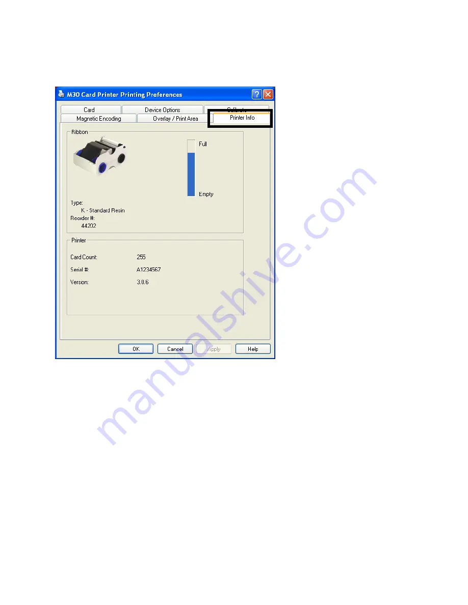
Using the Printer Information tab
Use the options on this tab to view information about the Ribbon installed in the Printer.
Page 1: ...Persona M30 Card Printer User Guide Rev 1 0 Single side Model Dual side Model Single side plus Mag Model Dual side plus Mag Model Part Number L000808 user guide ...
Page 2: ...ments guidelines and models for our technical training and user documentation At all times the Copyright Protection Notice for each document was adhered to within our Fargo documentation process This reference to other documents does not imply that Fargo is an ISO certified company at this time ANSI ISO ASQ Q9001 2000 American National Standard sub title Quality Management Systems Requirements pub...
Page 3: ...g the Printer front view Cartridge being installed ______________________________ 3 14 Connecting the Printer power_______________________________________________________ 3 15 Installing the Print Ribbon Cartridge _________________________________________________ 3 16 Installing Blank Cards into the Card Hopper ___________________________________________ 3 19 Lowering the Card Output Hopper_______...
Page 4: ...ng the Clean Printer Option_______________________________________________________ 5 7 Using the Test Print button__________________________________________________________ 5 9 Using the About button____________________________________________________________ 5 10 Using the Device Options tab M30 ____________________________________________________ 5 12 Reviewing the Device Options tab ___________...
Page 5: ...ibbon Information __________________________________________________ 5 64 Reviewing the Ribbon Level Indicator________________________________________________ 5 65 Using the Printer Calibration Utility ____________________________________________________ 5 66 Using the Image Darkness Option ___________________________________________________ 5 67 Using the Print Top of Form Option_________________...
Page 6: ...argo Card Printer was manufactured _________________________________ 9 2 Reviewing Example No 1 Serial Number 80453289_____________________________________ 9 2 Reviewing Example No 2 Serial Number A1280224 ____________________________________ 9 2 Section 10 Reviewing the Spare Parts List ____________________________________10 1 Reviewing the Persona M30 Spare Parts List____________________________...
Page 7: ...orrelative tables Table of Contents hyper linked You can use the automated Table of Contents to quickly locate for example an error message a procedure the index or an appendix Troubleshooting Replacement Removal Diagnostic and Navigation Procedures in hyper linked Sections You can go directly to Specifications General Troubleshooting Printer Adjustments Parts Replacement Printer Packing Board Lev...
Page 8: ... It may be damaged if exposed to static electricity discharges Information that raises potential electrostatic safety issues is indicated by a warning symbol as shown to the left To prevent equipment or media damage refer to the following safety messages before performing an operation preceded by this symbol To prevent equipment or media damage observe all established Electrostatic Discharge ESD p...
Page 9: ...Parts 1 Card Feed 6 Card Feed 13 Card Input Roller 2 Print Stepper 7 Ribbon Sensor 14 Cleaning Roller 3 Ribbon Drive 8 Ribbon Encoder 15 Card Feed Roller 4 Print Headlift 9 Headlift Sensor 16 Printhead Cooling Fan 5 Ribbon Rewind Motor 10 Printhead Thermistor 17 Card Input Hopper 11 Ribbon LED SNR 18 Magnetic Encoding Head Module 12 RFID Antenna 19 Platen Roller 20 Pinch Roller ...
Page 10: ...rmation is received from the PC 2 Printer checks the installed Ribbon type stored in memory against the Ribbon type command that was sent from the Printer a If Ribbon type does not match the RESUME button on the right will begin flashing 3 The Card Input Motor and Print Stepper Motor engage 4 The Card Feed Sensor detects leading edge of card and disengages the card input Motor Continued on the nex...
Page 11: ...s card to the middle of the platen Roller All Stop 10 The Print Headlift Motor engages 11 The Print Headlift Sensor detects closed state 12 The Print Headlift Motor disengages 13 The Print Stepper Motor engages 14 The Print Cover Sensor checks for a closed state 15 The Ribbon Drive Motor engages 16 The Image data is burned by the Printhead until image data is depleted All Stop 17 The Thermistor en...
Page 12: ...4 The Encoding data is written to the card 25 The Magnetic Encoder verifies while the Stepper reverses the card 26 After Ribbon advances a few encoder clicks assume Ribbon free of card All Stop 27 Repeat steps 9 through 23 for the appropriate number of color overlay panels 28 The Card is ejected from the singled sided Printer OR The Card Feed Stepper engages to queue the card for the Flipper Table...
Page 13: ... Sequence Step Process 1 On Power up the Printer checks the current state of the Card Feed Sensor and the Headlift Sensor 2 If the Headlift Sensor is found to be open the Headlift Motor will turn until a closed state is seen 3 If the Card Feed Sensor is found to be blocked the Card Feed Stepper will engage to eject the card ...
Page 14: ...to represent the Card Printer as CSA Certified under CSA Standard C22 2 No 60950 1 03 File Number E145118 FCC The Card Printer complies with the requirements in Part 15 of the FCC rules for a Class B digital device Note These requirements are designed to provide reasonable protection against harmful interference in a residential installation If equipment operation in a residential area causes unac...
Page 15: ...rd Sizes CR 80 3 375 L x 2 125 W 85 6mmL x 54mmW Accepted Card Thickness 20 mil and 30 mil 030 76mm Accepted Card Types PVC or polyester cards with polished PVC finish monochrome resin required for straight polyester Agency Listings Safety UL IEC 60950 1 2001 CSA C22 2 No 60950 1 03 Emissions CE FCC CRC c1374 EN 55022 Class B FCC Class B EN 55024 1998 EN 61000 3 2 and EN 61000 3 3 Card Input Hoppe...
Page 16: ...in Thermal Transfer Print Speed Print Speeds 7 seconds per card 514 cards per hour K 12 seconds per card 300 cards per hour KO Print speed indicates an approximate batch print speed and is measured from the time a card feeds into the printer to the time it ejects from the printer Print speeds do not include encoding time or the time needed for the PC to process the image Process time is dependent ...
Page 17: ...0 Hz 60 Hz System Requirements IBM PC or compatible Windows 2000 Window XP Pentium class 233 MHz computer with 64 MB of RAM or higher 200 MB free hard disk space or higher USB 1 1 Weight and Size Single sided weight 8 lbs 3 65 kg Single sided size 7 90 H x 13 62 W x 8 14 D 200mmH x 346mmW x 207mmD Dual sided weight 12 lbs 5 45 kg Dual sided size 7 9 H x 18 28 W x 8 14 D 200mmH x 465mmW x 207mmD ...
Page 18: ...ow each of these technologies works Function Description Resin Thermal Transfer Resin Thermal Transfer is the print method the Printer uses to print sharp black text and crisp bar codes which can be read by both infrared and visible light bar code scanners Used to print ultra fast one color ID cards on the Persona M30 Note Like dye sublimation this process uses the same thermal Printhead to transf...
Page 19: ...rrent print job and reset the Printer for the next print job If a card is left within the Printer after a print job is canceled it will automatically be ejected when the Printer is turned back ON Pause button The Pause button is used to pause the Printer during normal operation and also to resume operation after an error condition is cleared Note In general as the icon above this button indicates ...
Page 20: ...ard Resin Black K provides 1 000 prints This Ribbon provides high resin durability ideal for most general purpose monochrome ID card applications Resin black bar codes are readable by both infrared and visible light bar codes scanners Premium Resin Black K provides 1 000 prints This Ribbon provides maximum resin durability ideal for applications such as access control where cards are repeatedly sw...
Page 21: ...to poor print quality and will greatly reduce the life of the Printhead 2 Always store the card stock in its original packaging or in a clean dust free container 3 Do not print onto cards that have been dropped or soiled Note Printhead damage caused by contaminated or poor quality cards will automatically void the Printhead s factory warranty 4 If printing onto cards with a pre punched slot do not...
Page 22: ...letely smooth level surface in order for the Printer to achieve consistent color Coverage Certain types of Proximity cards have an uneven surface that will inhibit consistent color transfer Certain types of smart card chips are raised slightly above the cards surface which also results in poor color transfer UltraCard Stock Due to the importance of using high quality blank cards a factory approved...
Page 23: ...r User Guide Rev 1 0 2 10 Printer Module Flipper Table Module Assembly D900200 The Flipper Table Module Assembly D900200 is an automated Flipping Module that allows the Printer to print on the front side and backside of each card Display Flipper Table Module Assembly ...
Page 24: ...Here are references within this document See the Flipper Table Module Assembly Problems procedures See the Print Both Sides option under the Device Options tab as shown below See the Front and Back radio buttons under the Overlay Print Area tab as shown below See the Persona M30 Card Printer Service Manual for the replacement procedures for this Printer ...
Page 25: ... higher USB 1 1 Printer Setup and Installation Choosing a Good Location Follow these guidelines Place the unit in a location with adequate air circulation to prevent internal heat build up Use the Printer s dimensions as a guideline for the minimum clearances to the unit Note Allow for adequate clearance in front of the unit to accommodate the unit with its Covers open Do not install unit near hea...
Page 26: ...ure that no damage has occurred during shipping Make sure that all supplied accessories are included with your unit Check that the following items are included Power Supply US EU Power Cable Software Installation CD User Guide User Guide Warranty Statement Registration Card and Compliancy Document Reviewing the Printer front view Input Hopper Output Hopper Cartridge Bay ...
Page 27: ...RESTRICTED USE ONLY Fargo Electronics Inc Persona M30 Card Printer User Guide Rev 1 0 3 14 Reviewing the Printer front view Cartridge being installed ...
Page 28: ...nnect the Printer s USB cable until prompted during the Printer Driver installation Step Procedure 1 Plug the AC adapter power cable into the back of the Printer See the Display below 2 Plug the wall power cable into the AC power adapter 3 Plug the wall power cable into a standard 110VAC power outlet Display Shows back of Printer with AC power cable below ...
Page 29: ...ge The Fargo Persona M30 Card Printer uses a one piece disposable Ribbon Cartridge load system Every Ribbon Cartridge contains a Ribbon and a Card Cleaning Roller Step Procedure 1 To install the Ribbon Cartridge simply open the front Cover by pressing the black rubber pad or touch pad and lowering the Cover down as shown below ...
Page 30: ...per right arrow of display b Remove the Ribbon securing tape as shown in Display A middle right arrow of display 3 Slide the Ribbon Cartridge into the Printer as shown in this section 4 Raise the front Cover and press the front Cover s black rubber pad or touch pad to secure it Display A Shows the Print Ribbon Cartridge before it is installed or inserted into the Printer The Card Cleaning Roller s...
Page 31: ...STRICTED USE ONLY Fargo Electronics Inc Persona M30 Card Printer User Guide Rev 1 0 3 18 Installing the Print Ribbon Cartridge continued Display B Shows direction that Cartridge is inserted in the Printer ...
Page 32: ...le the magnetic strip up and towards the front of the Printer To print while using the Batch mode follow these instructions See further visual instructions below and on the next two pages Step Procedure 1 Open the Card Hopper Cover 2 Press the Card Hopper Load Lever down until the Card Tray locks into place 3 Load up to 100 cards into the Hopper with the print side down If using cards with a magne...
Page 33: ...ectronics Inc Persona M30 Card Printer User Guide Rev 1 0 3 20 Installing Blank Cards into the Card Hopper continued Press the Card Hopper Load Lever down Insert the cards Here the Lever is still up Here the Lever is pressed down ...
Page 34: ...TED USE ONLY Fargo Electronics Inc Persona M30 Card Printer User Guide Rev 1 0 3 21 Installing Blank Cards into the Card Hopper continued Here are the cards ready to insert Here the Input Hopper Door is closed ...
Page 35: ...rsona M30 Card Printer User Guide Rev 1 0 3 22 Lowering the Card Output Hopper Step Procedure 1 The Fargo Persona M30 comes with a Card Output Hopper to hold cards after they have been printed Pull the Output Hopper down until it snaps into place ...
Page 36: ...s document See the Flipper Table Module Assembly Problems procedures See the Print Both Sides option under the Device Options tab as shown below See the Front and Back radio buttons under the Overlay Print Area tab as shown below See the Persona M30 Card Printer Service Manual for the replacement procedures for this Printer Formatted Bullets and Numbering ...
Page 37: ... Card Printer User Guide Rev 1 0 3 24 Installing the Flipper Table Module Assembly D900200 Step Description 1 Caution Turn off the Printer and unplug the power cord from the Printer 2 Remove the Rear Cover D90066 to the Printer Continued on the next page ...
Page 38: ...a M30 Card Printer User Guide Rev 1 0 3 25 Installing the Flipper Table Module Assembly D900200 continued Step Description 3 Remove the Card Output or Exit Door D900092 and Left End Cap D900064 to the Printer as shown below Continued on the next page ...
Page 39: ... Flipper Table Module Assembly D900200 as shown below b Place the Flipper Table next to Printer 5 Connect the Flipper Table Module cable 6 Slide in the Flipper Table Module pins 7 Attach the Flipper Table Module pin screw 8 Use the Torx T 10 screwdriver to attach the one 1 front Baseplate mount screws F000170 9 Attach the Flipper Table Module Cover 10 Connect the USB and Power cables as shown belo...
Page 40: ... Installation CD into your computer s CD drive After a few seconds the CD s installer program will automatically open Follow the CD s on screen Procedures to complete installation Note If the CD does not automatically open use My Computer or Windows Explorer to view the contents of the CD Then double click on the Setup exe file listed on the CD 2 Click on the Install the Printer Driver button as s...
Page 41: ...TRICTED USE ONLY Fargo Electronics Inc Persona M30 Card Printer User Guide Rev 1 0 3 28 Installing the Printer Driver continued Step Procedure 3 Click on the Next button to continue with the Setup program ...
Page 42: ...ronics Inc Persona M30 Card Printer User Guide Rev 1 0 3 29 Installing the Printer Driver continued Step Procedure 4 Read the License Agreement Select the I accept the terms of the license agreement option and click Next to continue ...
Page 43: ...ng the Printer Driver continued Step Procedure 5 a Select the Complete option to install the following components Printer Driver Software Printer Driver User s Guide Fargo Diagnostics Utility Note Selecting Custom will provide the option to select which components to install b Click Next to continue ...
Page 44: ...RESTRICTED USE ONLY Fargo Electronics Inc Persona M30 Card Printer User Guide Rev 1 0 3 31 Installing the Printer Driver continued Step Procedure 6 Click Install to begin the installation ...
Page 45: ...SE ONLY Fargo Electronics Inc Persona M30 Card Printer User Guide Rev 1 0 3 32 Installing the Printer Driver continued Step Procedure 7 Wait while the M30 Card Printer is configuring your new software installation ...
Page 46: ...RESTRICTED USE ONLY Fargo Electronics Inc Persona M30 Card Printer User Guide Rev 1 0 3 33 Installing the Printer Driver continued Step Procedure 8 Click on Continue Anyway installation ...
Page 47: ...cs Inc Persona M30 Card Printer User Guide Rev 1 0 3 34 Installing the Printer Driver continued Step Procedure 9 a Select the port that your Printer is connected to at this time b Click on the OK button and continue with the installation ...
Page 48: ... Inc Persona M30 Card Printer User Guide Rev 1 0 3 35 Installing the Printer Driver continued Step Procedure 9 a Connect the USB cable to the Printer b Turn ON the Printer at this time if it is not already ON c Wait during the installation ...
Page 49: ...RESTRICTED USE ONLY Fargo Electronics Inc Persona M30 Card Printer User Guide Rev 1 0 3 36 Installing the Printer Driver continued Step Procedure 10 Select the installed Ribbon Type ...
Page 50: ...lling the Printer Driver continued Step Procedure 11 Click on the Finish button to complete the Setup 12 a Click on the YES button to exit the installer b Click on the NO button to return to the installer s main menu to install additional software components 13 You have completed the installation ...
Page 51: ...der the Printers window c Select Printing Preferences under the Printer drop down menu This will bring up the Persona M30 Printing Preferences window 2 a Select the Card tab and then click on the Test Print button as shown in Display A in this section Note Ensure that the Ribbon is installed before proceeding The correct Ribbon type is selected in the Device Options tab b When the Test Print butto...
Page 52: ...3 39 Printing a Test Print Image continued Step Procedure 3 This completes the Persona M30 Card Printer Encoder Installation Guide For additional help regarding the Test Print and other related items see the Persona M30 Card Printer Encoders User Guide located under Start Programs Fargo ...
Page 53: ...r User Guide Rev 1 0 3 40 Printer Transport Moving the Printer to another location Step Procedure 1 The Printer can be transported by gripping it under the back lid as shown in the photo below 2 You have completed the setup and installation procedures in this section ...
Page 54: ...ry make sure only qualified personnel perform these procedures Caution This device is electrostatically sensitive It may be damaged if exposed to static electricity discharges Information that raises potential electrostatic safety issues is indicated by a warning symbol as shown to the left To prevent equipment or media damage refer to the following safety messages before performing an operation p...
Page 55: ...as shown here IBM PC or compatible Windows 2000 XP Pentium class 233 MHz computer with 64 MB of RAM or higher 200 MB free hard disk space or higher USB Port 2 Confirm the correct installation of the Printer Driver a Close the software program and check the Printer Driver b Reboot the computer c Ensure the Printer Driver is installed correctly Note Especially if an obsolete Driver was recently remo...
Page 56: ...ile menu and select Page Setup 2 Click on the Printer button and select the Persona M30 Card Printer 3 Click OK and reset all four margins to zero Note The WordPad will automatically replace the values with its minimum margins 4 Open the program and type This is a Test then go to File on the menu bar and select Print 4 Determine whether there is adequate hard Drive space Note A large volume of tem...
Page 57: ... are in use in the Printer Resolving a Card Not Fed Error Cards will not feed off the Hopper Step Procedure 1 Review the following information Symptom Cards will not feed at all Printer Error State The card is not being detected by the Card TOF Sensor 11 seconds after the initiation of a print job causing the Printer to produce an error Driver Monitor Error Display Unable to Feed Card ...
Page 58: ... Step 3 3 Press the Cancel Print button on the Driver Monitor Error Display Message 4 Reboot the Printer by cycling the power 5 Check the Card Feed Motor a Remove all cards from the Hopper b Press the Card Hopper Load Lever down until the Card Tray locks into place c Using the Fargo Diagnostic utility send a test print to the Printer See below d Gently touch the Card Hopper Feed Roller to verify t...
Page 59: ...is securely connected to J 20 on the Printers Main Board c Ensure that the Card Hopper Feed Motor power cable is securely connected to the Card Hopper Feed Motor d Use the Fargo Diagnostic utility to send a test print to the Printer See below e If the Card Hopper Feed Motor is not moving continue to Step 8 8 Replace Card Hopper Feed Motor a Replace the Card Hopper Feed Motor b Use the Fargo Diagno...
Page 60: ... authorized supplies are in use in the Printer Step Procedure 1 Review the following information Symptoms Two or more cards feed at the same time causing the cards to jam at the Card Hopper Roller Printer is out of cards Printer Error State Card is not being detected by card TOF Sensor 11 sec after the initiation of a print job causing the Printer to produce an error Driver Monitor Error Display U...
Page 61: ...the Hopper with the print side down e Close the Card Hopper Cover to release the Card Tray f Press on the Resume button g If the cards do not feed continue to Step 3 3 Press the Cancel Print button on the Driver Monitor Error Display Message 4 Reboot the Printer by cycling the power 5 Check Card Feed TOF Sensor a Remove the Printers Rear Cover b Use a digital volt meter to place the Positive lead ...
Page 62: ...e in use in the Printer Step Procedure 1 Review the following information Symptom Printer RFID Sensor does not detect a recognizable signal from the Ribbon Printer Error State The Ribbon tag information is corrupted or incorrect Driver Monitor Error Display Ribbon RFID Error 2 Replace the Print Ribbon a Replace the Print Ribbon Cartridge b Press on the Resume button c If the error continues see th...
Page 63: ...n use in the Printer Step Procedure 1 Review the following information Symptom Printer RFID Sensor does not detect a recognizable signal from the Ribbon Printer Error State The Ribbon tag information is corrupted or incorrect Driver Monitor Error Display Ribbon RFID Error 2 Replace the Print Ribbon RFID Sensor a Replace the Print Ribbon RFID Sensor b Press on the Resume button c If the error conti...
Page 64: ... Error All Troubleshooting procedures assume that only factory authorized supplies are in use in the Printer Step Procedure 1 Review the following information Symptom The Printer is unable to verify encoded data Printer Error State The Printer is unable to verify encoded data Driver Monitor Error Display Mag Verify ...
Page 65: ...rd c Use a Magnetic Stripe reader or magnetic developer spray to determine if data is being written to the Magnetic Stripe d If data is not being written to the Magnetic Stripe Open the front Cover Remove the Magnetic Module Cover screw Remove the Magnetic Module Cover Verify that the Magnetic Module is seated securely into the Magnetic Module docking station e If the Magnetic Module is properly s...
Page 66: ...RESTRICTED USE ONLY Fargo Electronics Inc Persona M30 Card Printer User Guide Rev 1 0 4 13 Resolving the Mag Verify Error continued ...
Page 67: ...ing procedures assume that only factory authorized supplies are in use in the Printer Step Procedure 1 Review the following information Symptom There is not a Magnetic Encoder installed Printer Error State A print job with Magnetic encoding was sent with no Magnetic encoder installed in the Printer Driver Monitor Error Display No Mag Installed ...
Page 68: ...r b Remove the Magnetic Module Cover screw c Remove the Magnetic Module Cover d Verify that the Printer has a Magnetic Module installed Note If the Printer is equipped with a Magnetic Encoder Module ensure that it is seated securely into the Magnetic Module docking station If the issue persists replace the Magnetic Module See the Persona M30 service manual for replacement procedures 5 If the Print...
Page 69: ...that only factory authorized supplies are in use in the Printer NOTE Using the printer in direct sunlight may adversely affect the Ribbon Sensor integrity Step Procedure 1 Review the following information Symptom The Printer rolls through Ribbon and errors out Printer Error State The Printer cannot find the next panel on the Ribbon Driver Monitor Error Display Ribbon Sensor ...
Page 70: ...he take up roll 4 color panels past the damaged area 3 Press on the Resume button If the issue persists continue to Step 4 4 Replace the Ribbon Cartridge a Press on the Resume button b If the issue persists continue to Step 5 5 Press the Cancel Print button on the Driver Monitor Error Display Message 6 Reboot the Printer by cycling the power 7 Use the Driver Calibration tab to calibrate the Ribbon...
Page 71: ...are in use in the Printer NOTE Using the printer in direct sunlight may adversely affect the Ribbon Sensor integrity Step Procedure 1 Review the following information Symptom The Print Ribbon has become jammed or has broken in the Printer Printer Error State The Ribbon Supply Encoder Sensor has unexpectedly stop receiving information from the Ribbon Encoder Driver Monitor Error Display Ribbon Brea...
Page 72: ...me button b If the issue persists continue to Step 5 5 Use the Fargo Diagnostic utility to cycle the Printhead to ensure proper printhead operation See the Diagnostic button under the Card tab in your Printer Driver If the Printhead does not cycle properly see Resolving the Headlift Motor Sensor Error If the Printhead functions properly continue to Step 6 6 Replace the Ribbon Cartridge a Press on ...
Page 73: ...zed supplies are in use in the Printer NOTE Using the printer in direct sunlight may adversely affect the Ribbon Sensor integrity Step Procedure 1 Review the following information Symptom Printer will not print Printer Error State The Ribbon Sensor has detected the End Of Ribbon mark Driver Monitor Error Display Ribbon Out 2 Replace the Ribbon Cartridge a Press on the Resume button ...
Page 74: ...leshooting procedures assume that only factory authorized supplies are in use in the Printer Step Procedure 1 Review the following information Symptom Printer errors out as soon as it receives data from PC Printer Error State The Printer RFID Sensor is not receiving a signal from the Ribbon Driver Monitor Error Display No Ribbon Installed ...
Page 75: ...stalled in the Printer a Press on the Resume button b If the issue persists continue to Step 3 3 Remove the Rear Cover and check that the Ribbon RFID cable is securely connected to the Main Board J 5 and the RFID Sensor If the connections are loose reattach them Press on the Resume button If the connections are good or if the issue persists continue to Step 4 4 Replace the Ribbon RFID Sensor ...
Page 76: ...roubleshooting procedures assume that only factory authorized supplies are in use in the Printer Step Procedure 1 Review the following information Symptom Printer errors out as soon as it receives data from the PC Printer Error State The Ribbon installed does not match the Printer model Driver Monitor Error Display Invalid Ribbon ...
Page 77: ...signed for the correct Printer model 3 Press on the Resume button If the issue persists continue to Step 4 4 Remove the Rear Cover and check that the Ribbon RFID cable is securely connected to the Main Board J 5 and the RFID Sensor If the connections are loose reattach Press on the Resume button If the connections are good or if the issue persists continue to Step 5 5 Replace the Ribbon RFID Senso...
Page 78: ...hooting procedures assume that only factory authorized supplies are in use in the Printer Step Procedure 1 Review the following information Symptom Printer errors out as soon as it receives data from the PC Printer Error State The Ribbon installed does not match the Printer Driver information Driver Monitor Error Display Wrong Ribbon ...
Page 79: ...ht click on the M30 Card Printer and select Printing Preferences b Click on the Device Option tab c Click on the auto select button d Check that the Ribbon type matches the Ribbon selected 3 Press on the Resume button If the issue persists continue to Step 4 4 Remove the Rear Cover and check that the Ribbon RFID cable is securely connected to the Main Board J 5 and the RFID Sensor If the connectio...
Page 80: ...ving a Card Jam Error All Troubleshooting procedures assume that only factory authorized supplies are in use in the Printer Step Procedure 1 Review the following information Symptom Card is jammed Printer Error State Card TOF Sensor is detecting no card motion Driver Monitor Error Display Card Jam ...
Page 81: ...on continue to Step 4 3 Clearing a jammed card a If a card is jammed in the Printer use the Cancel button and the Pause button to move the Feed Rollers and free the card b The card can then be fed out of the Printer 4 Test the Card Sensor a Remove the Rear Cover b Using a Digital Voltmeter connect the negative lead to ground c Connect the positive lead to Pin 10 of J4 If blocked the Sensor should ...
Page 82: ...roubleshooting procedures assume that only factory authorized supplies are in use in the Printer Step Procedure 1 Review the following information Symptom The Printhead continuously cycles or does not cycle at all Printer Error State Headlift Sensor is not detecting movement from the Headlift Cam Driver Monitor Error Display General Error ...
Page 83: ... b Remove the back Cover c Verify that connection J20 is properly connected to the Main Board d If the Motor does not turn continue to Step 7 6 Test the Headlift Sensor a Remove the back Cover b Attach the positive lead from a Digital Voltmeter to Pin 1 of J9 Attach the negative lead to the Pin 3 of J9 If open the Sensor should read 0 17 to 0 9 VDC If closed the Sensor should read 4 9 to 5 5 VDC c...
Page 84: ...er Monitor Error Display None 2 Check for debris as follows a Open the front Cover and check that no debris has accumulated in the Sensor opening Use compressed air to clean the opening as needed b If the Sensor still does not work continue to Step 3 3 Check that the Sensor tab on the front Cover is not damaged a Open the front Cover and examine the Lid Sensor tab for damage if the Sensor tab is d...
Page 85: ... State None Driver Monitor Error Display None 2 Run a self test a Clear any card jams b Unplug power from the Printer c While holding down the Pause button reapply power Note A self test card will be printed 3 Look for an image on the Ribbon a After a self test has been run open the front Cover b Remove the Print Ribbon from the Printer c Visually inspect the set of panels that were last used by t...
Page 86: ...ting the Image Placement if a white border appears on the card adjust the image placement back toward its original value in increments of 2 until the white edge is gone i If still having blank card issues continue to Step 5 5 Check the Printhead connections a Remove the Printer power and USB cables b Turn the Printer over to gain access to the base plate c Remove the one 1 thumbscrew from the Prin...
Page 87: ...r b Using a Digital Voltmeter connect the negative lead to ground c Probe Pins 1 to 5 of the Printhead power connection on J16 d Ensure that a voltage between 22 to 23 VDC is read on each pin If less than 22 volts is read on any of the pins replace the Printhead If still having issue with blank cards replace the Main Board See the current Persona M30 User Guide for instructions on replacing the Ma...
Page 88: ...ocedures assume that only factory authorized supplies are in use in the Printer See the Installing the Flipper Table Module Assembly D900200 procedure as needed Step Procedure 1 Review the following information Symptom The Flipper Table Module Assembly is not functioning Printer Error State The Printer is unable to communicate with the Flipper Module Driver Monitor Error Display No Flipper Module ...
Page 89: ...ly factory authorized supplies are in use in the Printer See the Installing the Flipper Table Module Assembly D900200 procedure as needed Step Procedure 1 Review the following information Symptom The Flipper Table Module is jamming Printer Error State The Flipper Table has jammed while either aligning itself or flipping a card Driver Monitor Error Display Flipper Jam ...
Page 90: ... Cover a Clear any cards in the Flipper Table Module by using the Forward and or Reverse buttons located on the Printer s Top Cover b Ensure that the Flipper Table Module can rotate freely c Close the Printer s Flipper Table Module d Press the Resume button on the Printer s Top Cover to continue printing e To cancel the printing press the Cancel Print button from the Driver s display dialog ...
Page 91: ...1 Review the following information Symptom A thin line or scratch travels the entire length of the card See sample image below Printer Error State None Driver Monitor Error Display None 2 Check the card stock for scratches Replace the cards as needed 3 Examine the Printhead for visible damage 4 Clean the Printhead See the Cleaning the Printhead procedure 5 Replace the Printhead if the problem pers...
Page 92: ...eview the following information Symptom Prints have spots white or colored voids and or dust on them See sample image below Printer Error State None Driver Monitor Error Display None 2 Ensure the cards are clean and stored in a dust free environment Do not use cards with embedded contaminants in the surface 3 Clean the inside of the Printer See Cleaning the Printer s Interior 4 Clean the Cleaning ...
Page 93: ...uctions on changing the Printer s internal settings Step Procedure 1 Review the following information Symptom Printing is cut off or is not centered on the card or a white border appears Printer Error State None Driver Monitor Error Display None 2 Verify if the Image Position option within the Calibrate tab is set correctly or incorrectly a Open the Printer Control Panel from the Computer If using...
Page 94: ...RESTRICTED USE ONLY Fargo Electronics Inc Persona M30 Card Printer User Guide Rev 1 0 4 41 Resolving the Image Placement problems continued ...
Page 95: ...Horizontal Image Position Setting is set correctly or incorrectly See the graphic below If the white border is on the leading edge of the card adjust the Horizontal value by 2 If the white border is on the trailing edge of the card adjust the Horizontal value by 2 a Click on OK b Run a self test c If the white border is diminished continue the adjustment until it is gone ...
Page 96: ...e Position Setting is set correctly or incorrectly See the graphic below a Adjust the value as described below If the white border is on the top edge of the card adjust the Vertical value by 2 If the white border is on the bottom edge of the card adjust the Vertical value by 2 b Click on OK c Run a self test d If the white border is diminished continue the adjustment until it is gone ...
Page 97: ...n Symptom Photos on the cards look pixilated or grainy as shown below Printer Error State None Driver Monitor Error Display None 2 Use high resolution 24 bit color images to always capture an image at a 24 bit color setting at 300 dpi at the same size that it will be printed on the card as captured either with a scanner or with a digital camera If a small or low resolution image is stretched or bl...
Page 98: ...fy that a full color or Premium Resin Ribbon Cartridge is installed and that cards are properly loaded Caution If the power is ON disconnect the Power Cable from the Printer s rear panel 2 Press and hold the Pause Resume button 3 While holding down the Pause Resume button plug the power cable back into the Printer 4 Premium Resin Ribbon Cartridge installed The Printer will print a single color gra...
Page 99: ... or c a part has been replaced to check for proper Printer operation Step Procedure 1 Remove Ribbon Cartridge from the Printer and close the front Cover Caution If the power is ON disconnect the Power Cable from the Printer s rear panel 2 Press and hold the Pause Resume button 3 While holding down the Pause Resume button plug the power cable back into the Printer 4 The Printer will Encode magnetic...
Page 100: ...evice is electrostatically sensitive It may be damaged if exposed to static electricity discharges Information that raises potential electrostatic safety issues is indicated by a warning symbol as shown to the left To prevent equipment or media damage refer to the following safety messages before performing an operation preceded by this symbol To prevent equipment or media damage observe all estab...
Page 101: ...RESTRICTED USE ONLY Fargo Electronics Inc Persona M30 Card Printer User Guide Rev 1 0 5 2 M30 Print Driver Options Reviewing M30 Printer Drivers This section applies to the M30 Printer ...
Page 102: ...ches or mm option to choose the desired unit of measurement Note No 1 When designing a card format always set the card size or page size within the card design program to the exact dimensions of a CR 80 card or a CR 79 card Note No 2 The Card Size indicates that the Printer accepts standard credit card sizes CR 80 or CR 79 ISO ID 1 cards The dimensions of the total print area for this card size ap...
Page 103: ...Orientation Option Step Description 1 Select Portrait under Orientation to cause the card to print in a vertical orientation OR Select Landscape under Orientation to cause the card to print in a horizontal orientation Note An icon illustrating a printed card helps represent the difference between the two ...
Page 104: ...D USE ONLY Fargo Electronics Inc Persona M30 Card Printer User Guide Rev 1 0 5 5 Selecting the number of copies Step Description 1 Select the number of copies by clicking on the UP or DOWN arrows as shown below ...
Page 105: ...ED USE ONLY Fargo Electronics Inc Persona M30 Card Printer User Guide Rev 1 0 5 6 Using the Diagnostics button Step Description 1 Click on the Diagnostic button to bring up the Fargo Diagnostics Utility window ...
Page 106: ...Description 1 Click on the Clean Printer button to display the Clean Printer Utility window 2 Remove all cards from the Card Hopper and close the Hopper door 3 Open the Front Cover and remove the Ribbon Cartridge 4 Remove the paper backing from both sides of the Cleaning Card 5 Place the Cleaning card into the Single Feed Slot ...
Page 107: ...ev 1 0 5 8 Using the Clean Printer Option continued Step Description 6 Click on the Clean button at the bottom of the window Note The Printer will begin to feed the cleaning card through the card path 7 Reinsert the print Ribbon and cards after the cleaning procedure has completed ...
Page 108: ...g the Test Print button Step Description 1 Click on the Test Print button to send a simple self test print to the Printer Ensure that an appropriate Ribbon is installed for the M30 Ensure that the computer is effectively communicating with the Printer and that the Printer is functioning properly ...
Page 109: ...s Inc Persona M30 Card Printer User Guide Rev 1 0 5 10 Using the About button Step Description 1 Click on the About button to open a dialog box containing the copyright and version date code information about this Printer Driver software ...
Page 110: ...nics Inc Persona M30 Card Printer User Guide Rev 1 0 5 11 Using the About button continued Step Description 2 Review the dialog box containing the copyright and version date code information about this Printer Driver software as needed ...
Page 111: ...ED USE ONLY Fargo Electronics Inc Persona M30 Card Printer User Guide Rev 1 0 5 12 Using the Device Options tab M30 Reviewing the Device Options tab The M30 window with the Device Options tab is displayed below ...
Page 112: ...Ribbon Type option Use the Ribbon Type option to select Print Ribbons Step Description 1 Select the appropriate print Ribbon Type option from the dropdown menu for the type of Print Ribbon in use K Standard Resin K Premium Resin Colored Resin Metallic Resin KO Premium Resin Overlay BO Dye Sub Black Overlay ...
Page 113: ...ep Description 1 Click on the Auto Ribbon Select button to verify that the Ribbon type selected matches the Ribbon installed in the Printer The Printer Driver will change the Ribbon type to the correct setting or validate It will also display a dialog that it has changed the current setting or that the current Ribbon type is correct ...
Page 114: ...he appropriate dither method according to the type of image to be printed This option affects objects printed with a resin only print Ribbon Step Procedure 1 Select Optimized for Graphics when printing drawings and graphics e g clipart logos etc with resin OR Select Optimized for Photo when printing photo quality images with resin ...
Page 115: ...ith a resin only Ribbon by adjusting the Resin Heat slide Step Procedure 1 Adjust the Resin Heat Front K or the Resin Head Back K as needed Move the slide to the left to cause less heat to be used in the printing process causing resin images to be lighter or less saturated OR Move the slide to the right to a cause more heat to be used or b cause the resin image to be darker or more saturated Note ...
Page 116: ...when printing with the overlay panel of a Ribbon Note This control can be helpful for fine tuning the transfer of overlay onto the card Step Procedure 1 Move the slide to the left to cause less heat to be used in the printing process Note Certain card types may need additional heat for better transfer of the overlay material OR Move the slide to the right to cause more heat to be used ...
Page 117: ... Note The program must be able to send down two or more separate pages to be printed within the same document 2 Page 1 will be transferred to the front side of the card Page 2 will be transferred to the backside of the card Note The Printer Driver will always place all odd numbered pages on the front side of the card and all even numbered pages on the back side with this option selected If an odd ...
Page 118: ...Print Back Side First option Step Procedure 1 Select this option If you need to print the first page of a two page document on the backside of the card OR If you need to print the resin black on the chip side of the Smartcard The second page of the document will be printed on the front side of the card ...
Page 119: ...this option to print only onto the backside of cards Note Load the cards in the standard manner When this option is selected the Print Both Sides option is automatically disabled When attempting to print a two page document if Print Back Side Only is selected the first page of the document will print on the backside of the card The second page of the document will then be printed on the back of a ...
Page 120: ...ption to change the position of the printed image in relation to the set location of a card s Magnetic Stripe or smart chip Step Procedure 1 Select the Rotate Front 180 Degrees option to rotate the image on the front of the card by 180 degrees when printed OR Select the Rotate Back 180 Degrees option to rotate the image on the back of the card by 180 degrees when printed ...
Page 121: ...capabilities of the Printer Note This option still allows the Printer to encode cards Step Description 1 Select this option to encode or re encode cards to save time and avoid the use of printing supplies When this option is selected no print data will be sent to the Printer All encoding instructions will be sent based on how they are configured within the software ...
Page 122: ... Rev 1 0 5 23 Using the Calibrate tab Use the Calibrate tab to a control the position of the printable area in relation to the card b calibrate Sensors and c adjust the internal Printer settings that are customized for every Printer and saved directly within the Printer s memory ...
Page 123: ...ical and Horizontal adjustment arrows to adjust the Image Position values When adjusting these values keep in mind that cards always remain in the same position while moving through the Printer regardless of image orientation To illustrate this the card illustration shown in the Image Position box will flip and rotate according to the Portrait Landscape or Rotate 180 Degrees selection The outline ...
Page 124: ...ear of the Printer if a positive number is entered Move toward the front of the Printer if a negative number is entered OR Use the Horizontal adjustment to move the image Move toward the card output side of the Printer if a positive number is entered Move toward the card input side of the Printer if a negative number is entered Note No 1 The maximum value for the Vertical and Horizontal adjustment...
Page 125: ...onics Inc Persona M30 Card Printer User Guide Rev 1 0 5 26 Using the Sensors button Use the Sensors button to bring up a separate dialog box for calibrating the Printer s Ribbon Sensor see instructions in the Calibration window below ...
Page 126: ... Settings button Use the Settings button to bring up a separate dialog box for adjusting the internal Printer settings which are customized for every Printer at the factory and saved directly within the Printer s memory Note You can select the Restore Defaults to restore the internal default settings ...
Page 127: ...llowing describes these options and the Printer s magnetic encoding process The Card Printer comes with either a high coercivity factory installed Magnetic Stripe Encoding Module or a low coercivity Module The Printer cannot encode both types of Magnetic Stripes interchangeably within the same Printer Step Procedure 1 Select the Magnetic Encoding tab to display options for controlling the Magnetic...
Page 128: ...ext string prevents magnetic encoding Note This option may help correct encoding problems in all operating systems Step Procedure 1 Check this box to allow the Driver to process the fragmented text Select either High Co or Low Co radio buttons Step Procedure 1 Select either a high coercivity factory installed Magnetic Stripe Encoding Module or a low coercivity Module The Printer cannot encode both...
Page 129: ...ng process Note Although the default ISO Magnetic Track Options should be correct for almost all applications these options can be customized if the application requires it Step Procedure 1 Select a Track selection to a Change all options separately for each of the three individual tracks b Select the Default button for each of the separate tracks to set these options back to the ISO Standard sett...
Page 130: ...ach of the three magnetic tracks will encode Note No 1 They do not designate which tracks the Printer will encode e g to encode only Track 2 This must be done through the specific software program Note No 2 Although the Printer Driver will remember the settings specified for each of the three tracks the Printer Driver will always default to displaying the options for Track 1 whenever the Printer D...
Page 131: ...each of the Magnetic Stripe s three tracks Customize each track independently of the other two Specify which of the three tracks to customize by selecting one of the three track options Note No 1 After making the required selection the Magnetic Track Options box displays the current set of customization options for the selected track Note No 2 For most applications the default settings for these o...
Page 132: ...ttons Use this option to customize the Bit Recording Density Bits per Inch used to encode the magnetic data on the currently selected track Step Procedure 1 Select 75 BPI to change the bits per inch to 75 BPI OR Select 128 BPI to change the bits per inch to 128 BPI OR Select 210 BPI to change the bits per inch to 210 BPI ...
Page 133: ... the Character Data Size Bits per Character used to encode the magnetic data on the currently selected track Note This character size includes the parity bit if enabled Step Procedure 1 Select 5 Bits to change the bits per character to 5 BPC OR Select 7 Bits to change the bits per character to 7 BPC OR Select 8 Bits to change the bits per character to 8 BPC ...
Page 134: ...I Offset used to encode the magnetic data on the currently selected track Note This character offset value is subtracted from the ASCII value of each Magnetic Stripe data character prior to encoding on the track Step Procedure 1 Select NULL to change the ASCII Offset to NULL OR Select SPACE to change the ASCII Offset to SPACE OR Select ZERO to change the ASCII Offset to ZERO ...
Page 135: ...his option to shift the recorded magnetic data to the left hand side of the card s Magnetic Stripe OR Use this option for situations that require cards to be readable with insert type readers that may be unable to read the right hand side of the card Step Procedure 1 Select the Shift Data Left checkbox option to apply to all tracks ...
Page 136: ...eneration to none OR Select Even Parity to change the LRC Generation to Even Parity OR Select Odd Parity to change the LRC Generation to Odd Parity Using the Image Position radio buttons Use this option to customize the Image Position used to encode the magnetic data on the currently selected track Step Procedure 1 Select No Parity to change the Image Position to none OR Select Even Parity to chan...
Page 137: ... Rev 1 0 5 38 Reviewing the ISO Track Locations Review the magnetic encoding Module which encodes onto tracks in accordance with an ISO 7811 2 Magnetic Stripe Note Refer to the diagram below for track locations TRACK1 0 110 TRACK2 0 110 TRACK3 0 110 0 130 0 140 0 223 0 353 0 493 ...
Page 138: ...h track s maximum character capacity Caution When segmenting track data strictly use the appropriate Field Separator FS Sending the Track Information Magnetic track data is sent in the form of text strings from the application software to the Printer Driver along with all of the other printable objects within the card design Magnetic Track Data added In order for the Printer Driver to differentiat...
Page 139: ... Field Separator Valid Characters Maximum Number of Characters Track 1 ASCII 32 95 See the table below 78 Track 2 ASCII 48 63 See the table below 39 Track 3 ASCII 48 63 See the table below 106 Reviewing the Track Data Note Review this Note which displays how track the data should be entered for Tracks 1 2 and 3 Track Data Entry Sending data to Track 1 1 JULIE ANDERSON 623 85 1253 Sending data to T...
Page 140: ...ASCII Code Character ASCII Code Character ASCII Code Character 32 space 56 8 80 P 33 57 9 81 Q 34 58 82 R 35 No 59 83 S 36 60 84 T 37 61 85 U 38 62 86 V 39 63 87 W 40 64 88 X 41 65 A 89 Y 42 66 B 90 Z 43 67 C 91 44 68 D 92 45 69 E 93 46 70 F 94 47 71 G 95 _ 48 0 72 H 49 1 73 I 50 2 74 J 51 3 75 K 52 4 76 L 53 5 77 M 54 6 78 N 55 7 79 O ...
Page 141: ...lay O Panel and or the print area appear on a card Note This option is helpful if for example you would like to omit or block out the overlay or printing around a card s smart chip or Magnetic Stripe By default this option is set to print and overlay the entire card To customize the overlay and or print area select one of the options listed under Overlay Print Area ...
Page 142: ...uide Rev 1 0 5 43 Enabling the Print Both Sides option Step Procedure 1 Select the Print Both Sides checkbox under the Device Options tab to enable the Print Both Sides option under the Overlay Print Area Note This same selection applies to the K Panel Resin backside option ...
Page 143: ...v 1 0 5 44 Enabling the Print Back Side First option Step Procedure 1 Select the Print Back Side First checkbox under the Device Options tab to enable the Print Back Side First option under the Overlay Print Area Note This same selection applies to the K Panel Resin backside option ...
Page 144: ...lectronics Inc Persona M30 Card Printer User Guide Rev 1 0 5 45 Enabling the Front side option Overlay Print Area Step Procedure 1 Select the Front radio button which enables the Overlay Print Area and Security Options functions ...
Page 145: ...LY Fargo Electronics Inc Persona M30 Card Printer User Guide Rev 1 0 5 46 Enabling the Back side option Overlay Print Area Step Procedure 1 Select the Back radio button which enables only the Overlay Print Area function ...
Page 146: ...and or print only in the space outside the selected and defined area OR Select the Omit Smart Chip Area option for the Printer to overlay and or print only in the space outside the standard location of a smart chip OR Select the Omit Magnetic Stripe Area option for the Printer to overlay and or print only in the space outside the standard location of an ISO Magnetic Stripe OR Select the Omit Signa...
Page 147: ...ect For Print and Overlay for the defined area to apply to both the printing and overlay process OR Select For Overlay Only for the defined area to apply only to the overlay process Note In this mode printing will still be allowed over the entire card and only the overlay will be affected OR Select For Print Only No Overlay for the defined area to apply only to the print process Important In this ...
Page 148: ...ption Step Procedure 1 a Determine whether to use the Frontside option via the Front radio button or the Backside option via the Back radio button b Select the Defined Area s option to activate the card grid in the upper half of the window It is through this card grid that up to five 5 Defined Areas can be assigned ...
Page 149: ...he first defined area Determine the area of the card needed to define for a signature panel with a different size and location than the Driver s standard Omit Signature Area setting Note This area is indicated by the dashed outline Determine the area size by actually printing a card and looking at it in the same orientation as when it exits the Printer 3 Measure the total size of the desired area ...
Page 150: ...0 5 51 Using the Defined Area Option continued Step Procedure 4 Measure from the lower left corner of the card up and over to the lower left corner of for the defined area to begin and enter these values into the X and Y boxes Note The card grid lines are spaced at 2 inch 5mm intervals ...
Page 151: ...e Printer Note The location of a defined area is based on the card orientation as it exits the Printer b Measure the defined area location based on the printed card Note If selecting the Rotate Front 180 Degrees option the image will appear upside down as it exits the Printer c Position the defined area opposite to the measurement of the onscreen card design which will appear right side up Y 0 3 X...
Page 152: ...ghted with a dotted outline c Define another area by clicking on the Defined Area UP arrow Another 2 x 2 5mm x 5mm area will appear in the lower left hand corner Note This is the location in which all newly defined areas will first appear Up to 5 areas can be defined however additional areas cannot be added until the most recently created area has been moved or sized Note For this reason size and ...
Page 153: ...opdown menu list will be used to enable and select which type of visual security will be used The Visual Security dropdown list will be selectable only on the Front side see below Visual Security is not an option for the back side The following actions will occur when one of the Visual Security locations is selected The Overlay Print Area will be disabled The Security Options become selectable ...
Page 154: ...rsona M30 Card Printer User Guide Rev 1 0 5 55 Selecting Orientation Landscape Step Procedure 1 Select the Landscape radio button below under Orientation under the Card Size tab to use the Visual Security Solutions A to D as shown in this window ...
Page 155: ...Card Printer User Guide Rev 1 0 5 56 Selecting the Visual Security Solutions dropdown menu A to D Step Procedure 1 Click on the Visual Security Solutions dropdown menu below under the Landscape Orientation see above to use the options shown in this display ...
Page 156: ...ersona M30 Card Printer User Guide Rev 1 0 5 57 Selecting Orientation Portrait Step Procedure 1 Select the Portrait radio button below under Orientation under the Card Size tab to use the Visual Security Solutions E to H as shown in this window ...
Page 157: ...ona M30 Card Printer User Guide Rev 1 0 5 58 Selecting the Visual Security Solutions dropdown menu E to H Step Procedure 1 Click on the Visual Security Solutions dropdown menu under the Portrait Orientation see above to use the options shown below ...
Page 158: ... option only Step Procedure 1 Click on either the VeriMark or HoloMark radio button as shown below The foil options are used to control the size of the exclusion area Note When VeriMark is selected a rectangle sized area is excluded HoloMark uses a square sized area 2 Click on the VeriMark radio button below for the rectangle sized area ...
Page 159: ...ONLY Fargo Electronics Inc Persona M30 Card Printer User Guide Rev 1 0 5 60 Selecting the HoloMark radio button Frontside option only Step Procedure 1 Click on the HoloMark radio button below for the squared area size ...
Page 160: ...tom Graphic in a 2D foil The custom VeriMark image is stamped on blank standard sized cards You can select one of eight positions A to H as shown in the Portrait and Landscape samples below Sample 1 VeriMark Card Landscape Orientation 4 positions below A D B C Sample 2 VeriMark Card Portrait Orientation 4 positions below F E G H ...
Page 161: ...tom Graphic in a 2D foil The custom HoloMark image is stamped on blank standard sized cards You can select one of eight positions A to H as shown in the Portrait and Landscape samples below Sample 1 HoloMark Card Landscape Orientation 4 positions below D C B A Sample 2 HoloMark Card Portrait Orientation 4 positions below F E G H ...
Page 162: ...CTED USE ONLY Fargo Electronics Inc Persona M30 Card Printer User Guide Rev 1 0 5 63 Using the Printer Information tab Use the options on this tab to view information about the Ribbon installed in the Printer ...
Page 163: ...Fargo Electronics Inc Persona M30 Card Printer User Guide Rev 1 0 5 64 Reviewing the Ribbon Information Step Procedure 1 Use the Ribbon information to determine which Ribbon is being used to print with and its part number ...
Page 164: ... USE ONLY Fargo Electronics Inc Persona M30 Card Printer User Guide Rev 1 0 5 65 Reviewing the Ribbon Level Indicator Step Procedure 1 Use the Ribbon Level indicator to view approximately how much Ribbon is left ...
Page 165: ...the adjustment mode to change the Printer s internal settings Note The Card Printer is equipped with an internal adjustment mode programmable through the Settings dialog box This dialog box is accessible only if the Printer is powered ON it is in Ready Mode and it is properly connected to the PC Caution These settings are optimized at the factory In most cases these settings can be used without ch...
Page 166: ...easing or decreasing the amount of heat used by the Printhead when printing Step Procedure 1 Lighten the printed image by clicking the down arrow to enter a negative value and decrease the amount of Printhead heat OR Darken the image by clicking the up arrow to enter a positive value and increase the amount of Printhead heat Caution If the value is set too high the Ribbon may jam or even break ...
Page 167: ...e will move in relation to the fixed card position as a positive or negative Image Placement value is entered Step Procedure 1 Enter a negative value to move the printed image toward the leading edge of the card or the card output to the side of the Printer OR Enter a positive value to move the printed image toward the trailing edge of the card or the card input to the side of the Printer Maximum ...
Page 168: ...ion as a positive or negative Print End of Form value is entered Step Procedure 1 Enter a negative value to reduce the Print End of Form and move the end of the printable area more toward the leading edge of the card OR Enter a positive value to increase the print length and move the end of the printable area more toward the trailing edge of the card Maximum Adjustment Range The maximum adjustment...
Page 169: ...nd that cards always remain in the same landscape orientation while moving through the Printer Step Procedure 1 Enter a negative value to move the image towards the bottom edge of the card See the image below OR Enter a positive value to move the image towards the back top edge of the card see image below Maximum Adjustment Range The maximum adjustment range is 127 As a rule 10 equals about 030 8m...
Page 170: ...c for Hi Co Magnetic cards and 2 54vdc for Lo Co Magnetic cards Depending on the cards that are being used it may be necessary to adjust the encoder voltage out of default See the next two procedures for instructions on adjusting the Magnetic Encoder Voltage Note The required encoder voltage for the cards will need to be known in order to properly set the Encoder Voltage Offset value This informat...
Page 171: ... to properly set the Encoder Voltage Offset value This information should be available through the card manufacturer or reseller 2 Use the following equation to identify the proper Mag Hi Co Voltage Offset value 36500 Desired Voltage 4 6 1 23 1 2670 39 0625 40 X 1 For example Required Encoder Voltage 9vdc 36500 9 4 6 1 23 1 2670 39 0625 40 X 1 15 3 Change the Mag Hi Co Voltage Offset value I E 15 ...
Page 172: ... properly set the Encoder Voltage Offset value This information should be available through the card manufacturer or reseller 2 Use the following equation to identify the proper Mag Lo Co Voltage Offset value 36500 Desired Voltage 4 6 1 23 1 2670 39 0625 126 X 1 For example Required Encoder Voltage 1 5vdc 36500 1 5 4 6 1 23 1 2670 39 0625 126 X 1 42 3 Change the Mag Lo Co Voltage Offset value I E ...
Page 173: ...Note For this diagram imagine that the card is transparent and the card s Magnetic stripe can be seen through the top or front side of the card Step Procedure 1 Enter a negative value to move the start of the magnetic data more toward the leading edge of the card or the card output to the side of the Printer OR Enter a positive value to move the start of the magnetic data toward the trailing edge ...
Page 174: ...RESTRICTED USE ONLY Fargo Electronics Inc Persona M30 Card Printer User Guide Rev 1 0 5 75 Using the Mag Top of Form Option continued ...
Page 175: ...Procedure 1 Use the Ribbon Tension option to increase or decrease the amount of tension drag on the Ribbon during printing Enter a positive value to increase the amount of tension that is placed on the Ribbon during printing OR Enter a negative value to decrease the amount of tension that is placed on the Ribbon during printing ...
Page 176: ... the Flipper Center Offset Option Use this option to change the card position on the Flipper Table relative to the center for flipping Note This is important to maintain the proper clearance with surrounding objects when flipping a card Step Procedure 1 Enter a negative value to position a card closer to the output of the Printer when the Flipper is in home horizontal position Or Enter a positive ...
Page 177: ...ke sure only qualified personnel perform these procedures Caution This device is electrostatically sensitive It may be damaged if exposed to static electricity discharges Information that raises potential electrostatic safety issues is indicated by a warning symbol as shown to the left To prevent equipment or media damage refer to the following safety messages before performing an operation preced...
Page 178: ...ng Kit This Cleaning Kit provides you with the specialized cleaning supplies and the required cleaning procedures for you to maintain your Persona M30 Card Printer Encoders The following cleaning procedures will require less than ten minutes For more thorough cleaning instructions please refer to the Cleaning Section in the appropriate User Guide Four 4 Printhead Cleaning Swabs are pre moistened w...
Page 179: ... consistent print quality Step Procedure 1 Open the Printer s Front Cover 2 Remove the Print Ribbon 3 Squeeze the Printhead Cleaning Swab to saturate the tip of the swab with alcohol 4 Use the Printhead Cleaning Swab to gently rub back and forth over the entire length of the Printhead 3 to 4 times 5 Once the Printhead is completely dry replace the Ribbon and close the Front Cover ...
Page 180: ...y every 1000 prints to maintain a consistent print quality Note The Card Feed Rollers move the card throughout the print process Rollers should be kept clean to prevent card jams and card contamination This cleaning process will ultimately lead to better print quality and extended Printhead life Step Procedure 1 Open the Printer s Front Cover and remove the Print Ribbon ...
Page 181: ...ll the cards from the Printer s Input Hopper 3 Use the Cleaning Card from the Printer s and remove the adhesive backing from both sides of the card Note If your Printer has a Magnetic Encoder installed be sure to leave the small Liner Strip on top of the Cleaning Card in place This small strip is needed to protect the Magnetic Head from the adhesives on the Cleaning Card ...
Page 182: ... and the Card Feed Rollers continued Step Procedure 4 Insert the Cleaning Card into the Single Feed Card Slot until the card stops Note If your Printer is equipped with a Magnetic Encoder you must insert the Cleaning Card with the printed side up and with the small Liner Strip towards the front of the Printer ...
Page 183: ...ill then perform an automated cleaning procedure This procedure is designed to thoroughly clean the Platen and the Card Feed Rollers inside the Printer Cleaning the Printer s Interior Periodically use a Cleaning Pad from the Printer s Cleaning Kit to remove dust and other contaminants from inside the Printer Note Dust and other particles may accumulate inside the Printer with continued usage This ...
Page 184: ... specific packing procedure for this Card Printer Follow this instruction to pack the Card Printer for transport Step Procedure 1 Clean the inside of the Printer with compressed air 2 Wipe it down with a lint free cloth 3 Clean the Printhead with a alcohol swab 4 Pack the Printer in the original carton and packing materials 5 Ensure to enclose any necessary paperwork test cards etc ...
Page 185: ...ion 8 Firmware Upgrades Introduction The Persona M30 Card Printer Encoders Firmware Upgrade Document Rev 1 0 and this section are identical They both provide step by step procedures for upgrading the Firmware on these Printers Requirements Windows 32 bit Operating System XP 2000 Internet Access ...
Page 186: ...It may be damaged if exposed to static electricity discharges Information that raises potential electrostatic safety issues is indicated by a warning symbol as shown to the below To prevent equipment or media damage refer to the following safety messages before performing an operation preceded by this symbol To prevent equipment or media damage observe all established Electrostatic Discharge ESD p...
Page 187: ... Guide Rev 1 0 8 3 Downloading Firmware Step Procedure 1 Open the Fargo Diagnostic Utility located in the Programs folder as shown below Click on the Start icon on the desktop Select the Programs folder Select the Fargo folder Click on the Diagnostic Utility as shown below ...
Page 188: ...ESTRICTED USE ONLY Fargo Electronics Inc Persona M30 Card Printer User Guide Rev 1 0 8 4 Downloading Firmware continued Step Procedure 2 Click on the Download Firmware button under Step 1 as shown below ...
Page 189: ...Y Fargo Electronics Inc Persona M30 Card Printer User Guide Rev 1 0 8 5 Downloading Firmware continued Step Procedure 3 a Check that the Computer has an active Internet connection b Click on the Yes button as shown below ...
Page 190: ...na M30 Card Printer User Guide Rev 1 0 8 6 Downloading Firmware continued Step Procedure 4 This will launch the Fargo Support page Click on the Firmware selection box Use the drop down menu to select the Printer Click on the Go button as shown below ...
Page 191: ...e file to the computer s Desktop as shown below 8 Click on the Close button to close this dialog when the download is completed as shown below 9 From the computer s desktop double click on the Firmware exe file to un zip it as shown below 10 Click on the Browse button on the WinZip Self Extractor window as shown below 11 Select the Desktop then click on the OK button in the Browse for Folder dialo...
Page 192: ...ing Firmware continued Step Procedure 13 Click on the Select Firmware File button under Step 2 in the Fargo Diagnostic Utility window as shown below 14 Select the Desktop dropdown menu Click on the frm file Click on the Open button as shown below 15 This completes the Downloading Firmware procedure ...
Page 193: ...rinter User Guide Rev 1 0 8 9 Sending the Firmware File Step Procedure 1 From the Fargo Diagnostic Tool click on the Send Firmware button as shown below 2 Upon successful completion of the Firmware Update the Printer will restart 3 The procedure is now completed ...
Page 194: ...ontacting Fargo Technical Support Step Procedure 1 Refer to Section 3 General Troubleshooting as needed Contact the Fargo Technical Support Group by phone at 952 941 0050 or by fax at 952 941 1852 for additional technical assistance OR Contact Fargo Technical Support via the Web http www fargosupport com 2 Position a phone near the Printer and Computer so Fargo technicians can help to troubleshoot...
Page 195: ...e built Reviewing Example No 1 Serial Number 80453289 1 80453289 The first two digits in the serial number indicate the year the Printer was built e g the digits 80 indicate the year 1998 2 80453289 The third and fourth digits in the serial number indicate the week the Printer was built e g the digits 45 indicate week 45 of that year 3 80453289 The last four digits indicate the sequence number for...
Page 196: ...inter User Guide Rev 1 0 10 1 Section 10 Reviewing the Spare Parts List Reviewing the Persona M30 Spare Parts List Persona M30 ID Card Printer Recommended Spare Parts List Effective Date June 2004 For current pricing see http www fargopartner com support_services ...
Page 197: ... A type of color matching that takes the color values of pixels and applies them to an algebraic equation to adjust the levels of hue saturation and brightness ANSI American National Standards Institute The United States Representative to ISO providing standardization for U S Manufactures prior or in addition to acceptance by ISO AS400 An IBM operating system running on a main frame DTC500 Fargo P...
Page 198: ...hip based non volatile memory Bit An abbreviation for binary digit Each bit is an element of information that can have two states off and on Bit map A graphic produced by an array of pixel elements with the color hue brightness and saturation information stored in bits The more bits the more values and thus the greater variety 1 bit color is black and white 8 bit color produces 256 shades of gray ...
Page 199: ...for dedicated high speed communication between the PC and the Printer port Centronics A parallel communications interface that has become the standard for connections to Printers designed by the Centronics Corp Coercivity The property of a Magnetic Stripe that indicates the amount of force needed before magnetic saturation measured in Oersteds Oe Color matching The process of adjusting color hue s...
Page 200: ...erial port interfaces DC Motor A Motor that works on DC with continuous motion DC Direct Current Electronic flow that is unidirectional flowing from the positive to negative of a power source Default A setting or parameter that comes preset from the factory in Driver or firmware Performance parameters may be customized in the Driver but can be reset to the factory values usually through the push o...
Page 201: ...evice and is connected in serial to the parallel cable Dot The smallest unit of an image that the Printer is able to produce The smaller the dot see dot pitch the sharper the image Dot pitch A measurement of image sharpness denoting the width of the dots that make up a pixel The smaller the pitch the sharper the image Download The transfer of a data file from one device to the other over a network...
Page 202: ...d with built in electronic devices such as smart cards or prox cards E card Docking Station The device in the Printer that accepts smart cards with an ISO smart card contact station This allows the user to write to the smart card chip with a standard RS 232 interface in the back of the Printer or with the optional built in encoder Edge to Edge Refers to the maximum printable area on a card resulti...
Page 203: ...ncrease the port throughput EPROM Electronically Programmable Read Only Memory A microchip based non volatile memory storage device that cannot be rewritten in the field Firmware for many Fargo Printers is stored on these chips and so a change of the chip is necessary for an upgrade Escape sequence A string or control character that indicates to the processor that what follows is a command and not...
Page 204: ...istic curve relating optical density to relative log exposure Glossy Matte A smooth polished surface in comparison to a rougher matte surface Fargo matte cards have a surface index Ra of approximately 65 microinches while glossy have a Ra 3 Glossy PVC A card made of PVC with a smooth polished surface Surface roughness of approximately 0 10 micro inches This is required for direct to card dye subli...
Page 205: ...match Head Abbreviation for Printhead Heat sink A device used to dissipate heat into the ambient Heat Seal A resinous film transferred by the Printhead onto the back of an HDP intermediate transfer film to facilitate adhesion HiCo High Coercivity The coercivity value of magnetic media between 2500 4000 Oe ISO 7811 6 Fargo s High Coercivity encodes at 2750 Oe HTML HyperText Markup Language A standa...
Page 206: ...by the Printhead The film is then transferred to the card surface by the hot lamination Roller ISO From the Greek iso meaning same It is used to represent data from the International Organization for Standardization JIS II Japanese Industrial Standard The standard for encoding to a Magnetic Stripe provided by the Japan Standards Association The single track is as wide as ISO tracks 1 and 2 combine...
Page 207: ...Co Low Coercivity The coercivity value of magnetic media between 250 600 Oe ISO 7811 2 Fargo s Low Coercivity encodes at 300 Oe LPT Port Line Printer Port The system abbreviation for a PC s parallel Printer port Magnetic encoding The process of orienting successive magnetic bits to produce a serial data string Magnetic stripe An area of the card with an applied or impregnated ferrous material that...
Page 208: ...the science of electromagnetism Offset The prescribed distance between a reference point and the target point The offset in card printing may refer to the position of the image relative to the leading edge or the distance of the start of magnetic encoding from the leading edge of the card O Ring A rubber ring used as a belt in several media driving applications OS Operating System The instructions...
Page 209: ...er in which serial data is divided into sections and sent simultaneously down parallel wires to speed transfer rate Parallel port A communication socket on a device that allows for parallel data transfer PC Personal Computer A stand alone programmable electronic device that can store retrieve and process data consisting of a CPU mouse keyBoard and monitor PCB Printed Circuit Board A solid multi la...
Page 210: ...ester material that enhances card security and durability applied over the printed surface with a hot Roller Available as clear or with embedded holographic type security images Portrait A document layout that is viewed with the document s long axis in a vertical orientation Potentiometer An electronic resistor with a variable resistance value that can be mechanically set Print Driver A software u...
Page 211: ... reader mounted on the e card docking station inside the Printer encoder The ProxPoint is a read only device producing a Wiegand signal that is converted to RS 232 using a Cypress Computer Systems CVT 2232 Application programs can read information from HID prox cards via a RS 232 signal through a dedicated DB 9 port on the outside of the Printer labeled Prox RAM Random Access Memory A storage devi...
Page 212: ...del Ribbon The dye impregnated film that is used for color printing Ribbon cable Parallel wires held flat in a row by plastic insulation RibbonTraq A Fargo Electronics method of placing bar code like marks on the transition area between color panels These marks are arranged for detection by a reflective Sensor array for the identification of Ribbon type and the Ribbon position RMA number Return Me...
Page 213: ...talls in a slot on the main Board Simplex Single sided printing SmartGuard An application from Fargo Electronics that allows users to prevent access to the Printer through the use of a personally encoded smart card SmartGuard SmartGuard is a Printer security option that uses a custom access card and a built in reader to restrict Printer access Only a valid access card can enable the Printer to pri...
Page 214: ...urge Protector An electronic device placed in serial to the Printer s power supply that prevents damage to the Printer from electronic surges and electrical current that is outside of the normal parameters Switch box An electromechanical device to which a user may connect several peripheral devices to the parallel port simultaneously while using the selector switch to designate the active port TAC...
Page 215: ...netic data string Troubleshooting The process of investigating and determining the cause of a problem TrueType TT A font format that produces each character using a mathematical equation rather than a graphical representation resulting in a much sharper cleaner image UltraCard The Fargo brand of card stock recommended for use in Fargo Printers with the necessary glossy surface and composed of PVC ...
Page 216: ...e order in which they are printed Yellow Y Magenta M Cyan C YMCK The designation of colored Ribbon by the panels of color in the order in which they are printed Yellow Y Magenta M Cyan C Black K YMCKH The designation of colored Ribbon by the panels of color in the order in which they are printed Yellow Y Magenta M Cyan C Black K Heat Seal H YMCKK The designation of colored Ribbon by the panels of ...
Page 217: ...scratches 4 38 Card Surface 2 9 cards look pixilated or grainy 4 44 card s Magnetic Stripe smart chip 5 21 CD Compact Disc 11 3 Centronics 11 3 Character 5 40 Character ASCII Offset 5 35 Character Parity 5 37 Character Size radio buttons 5 34 Cleaning Inside Printer 4 39 Cleaning Roller 11 3 Cleaning the Printhead 4 38 Clear Protective Overlay Panel 2 7 Coercivity 11 3 Color matching 11 3 Colored ...
Page 218: ...e Array 11 8 Front and Back radio buttons 2 11 3 23 Front Cover 2 6 Frontside and Backside options Overlay Print Area 5 43 5 44 Full bleed 11 8 Full Card option 5 47 G Gamma 11 8 Glossy Matte 11 8 Glossy PVC 11 8 Graphical Device Interface GDI 11 8 Gray Scale 11 8 H Halftoning 11 8 Hard Drive 11 9 hard Drive space adequate or inadequate 4 3 HDP High Definition Printing 11 9 Head 11 9 Headlift Moto...
Page 219: ... Output 11 12 Output Hopper 11 12 Overlaminate 11 13 Overlay 11 12 Overlay Print Area 5 50 5 51 Overlay Print Area options 5 48 Overlay Print Area tab 5 42 Oversized Cards 11 13 P Parallel 11 13 Parallel port 11 13 Pause button and LED 2 6 Pause Resume button 4 45 4 46 PC Personal Computer 11 13 PCB Printed Circuit Board 11 13 Peel 11 13 Peel Off 11 13 Peripheral 11 13 PET 11 14 Photo 5 15 Pinch R...
Page 220: ...e 11 17 Settings button 4 42 4 43 Shift Data Left checkbox 5 36 Shift Data Left option 5 36 SIMM 11 17 Simplex 11 17 Smart Card 11 17 SmartGuard 11 17 SmartShield 11 17 Software 11 17 special precautions 1 2 5 1 6 1 Spooler 11 17 Spooling 11 18 SS Start Sentinel 11 18 Stacker 11 18 Standard Resin Black K 2 7 Standard Self test YMC 4 45 Start Sentinel SS 5 39 Stepper Motor 11 18 String 11 18 Supply...
Page 221: ...RICTED USE ONLY Fargo Electronics Inc Persona M30 Card Printer User Guide Rev 1 0 12 5 WordPad 4 3 Wrinkle 11 20 X X and Y boxes 5 51 Y YMC 11 20 YMCK 11 20 YMCKH 11 20 YMCKK 11 20 YMCKO 11 20 YMCKOK 11 20 ...