background image

82

WORKSHOP MANUAL 

TL 250

CHAPTER 15

ELECTRICAL DEVICES

11  Diagnostics

111

WORKSHOP MANUAL

CHAPTER 11

DIAGNOSTICS

250 Rev00 / 2019

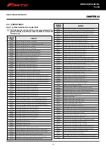
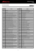
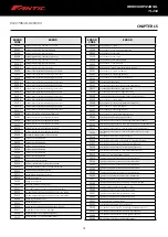
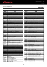
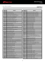
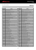
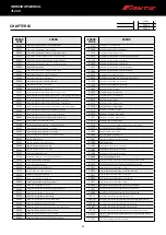
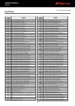
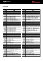
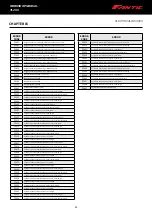
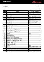
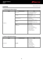
ERROR 

CODE

ERROR

P208B

Reductant Pump Control Range/Performance

P208C

Reductant Pump Control Circuit Low

P208D

Reductant Pump Control Circuit High

P208E

Reductant Injection Valve Stuck Closed Bank 1 Unit 1

P208F

Reductant Injection Valve Stuck Closed Bank 2 Unit 1

P2090

B Camshaft Position Actuator Control Circuit Low (Bank 1)

P2091

B Camshaft Position Actuator Control Circuit High (Bank 1)

P2092

A Camshaft Position Actuator Control Circuit Low (Bank 2)

P2093

A Camshaft Position Actuator Control Circuit High (Bank 2)

P2094

B Camshaft Position Actuator Control Circuit Low (Bank 2)

P2095

B Camshaft Position Actuator Control Circuit High (Bank 2)

P2096

Post Catalyst Fuel Trim System Too Lean Bank 1

P2097

Post Catalyst Fuel Trim System Too Rich Bank 1

P2098

Post Catalyst Fuel Trim System Too Lean Bank 2

P2099

Post Catalyst Fuel Trim System Too Rich Bank 2

P209A

Reductant Injection Air Pressure Sensor B Circuit

P209B

Reductant Injection Air Pressure Sensor B Circuit Range/Performance

P209C

Reductant Injection Air Pressure Sensor B Circuit Low

P209D

Reductant Injection Air Pressure Sensor B Circuit High

P209E

Reductant Injection Air Pressure Sensor A/B Correlation

P209F

Reductant Tank Heater Control Circuit Performance

P20A0

Reductant Purge Control Valve Circuit /Open

P20A1

Reductant Purge Control Valve Performance

P20A2

Reductant Purge Control Valve Circuit Low

P20A3

Reductant Purge Control Valve Circuit High

P20A4

Reductant Purge Control Valve Stuck Open

P20A5

Reductant Purge Control Valve Stuck Closed

P20A6

Reductant Injection Air Pressure Control Valve Circuit/Open

P20A7

Reductant Injection Air Pressure Control Valve Performance

P20A8

Reductant Injection Air Pressure Control Valve Circuit Low

P20A9

Reductant Injection Air Pressure Control Valve Circuit High

P20AA

Reductant Injection Air Pressure Control Valve Stuck Open

P20AB

Reductant Injection Air Pressure Control Valve Stuck Closed

P20AC

Reductant Metering Unit Temperature Sensor Circuit

P20AD

Reductant Metering Unit Temperature Sensor Circuit Range/Performance

P20AE

Reductant Metering Unit Temperature Sensor Circuit Low

P20AF

Reductant Metering Unit Temperature Sensor Circuit High

P20B0

Reductant Metering Unit Temperature Sensor Circuit Intermittent/Erratic

P20B1

Reductant Heater Coolant Control Valve Circuit/Open

P20B2

Reductant Heater Coolant Control Valve Performance

P20B3

Reductant Heater Coolant Control Valve Circuit Low

P20B4

Reductant Heater Coolant Control Valve Circuit High

P20B5

Reductant Metering Unit Heater Control Circuit/Open

P20B6

Reductant Metering Unit Heater Control Circuit Performance

P20B7

Reductant Metering Unit Heater Control Circuit Low

P20B8

Reductant Metering Unit Heater Control Circuit High

P20B9

Reductant Heater A Control Circuit/Open

P20BA

Reductant Heater A Control Circuit Performance

P20BB

Reductant Heater A Control Circuit Low

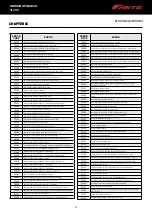
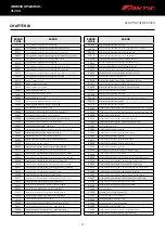
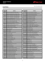
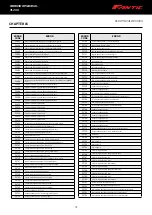
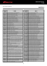
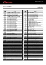
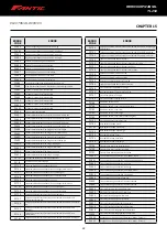
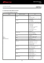
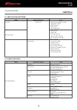
ERROR 

CODE

ERROR

P205B

Reductant Temperature Sensor Circuit Range/Performance

P205C

Reductant Tank Temperature Sensor Circuit Low

P205D

Reductant Tank Temperature Sensor Circuit High

P205E

Reductant Temperature Sensor Circuit Intermittent

P205F

Reductant System Performance Bank 2

P2060

Reductant Injection Air Pump Control Circuit Low

P2061

Reductant Injection Air Pump Control Circuit High

P2062

Reductant/Regeneration Supply Control Circuit/Open

P2063

Reductant/Regeneration Supply Control Circuit Low

P2064

Reductant/Regeneration Supply Control Circuit High

P2065

Fuel Level Sensor B Circuit

P2066

Fuel Level Sensor B Performance

P2067

Fuel Level Sensor B Circuit Low

P2068

Fuel Level Sensor B Circuit High

P2069

Fuel Level Sensor B Circuit Intermittent

P206A

Reductant Quality Sensor Circuit

P206B

Reductant Quality Sensor Circuit Range/Performance

P206C

Reductant Quality Sensor Circuit Low

P206D

Reductant Quality Sensor Circuit High

P206E

Intake Manifold Runner Control Stuck Open (Bank 2)

P206F

Intake Manifold Runner Control Stuck Closed (Bank 2)

P2070

Intake Manifold Tuning (IMT) Valve Stuck Open

P2071

Intake Manifold Tuning (IMT) Valve Stuck Closed

P2074

Manifold Absolute Pressure/Mass Air Flow - Throttle Position Correlation 

at Higher Load

P2075

Intake Manifold Tuning (IMT) Valve Position Sensor/Switch Circuit

P2076

Intake Manifold Tuning (IMT) Valve Position Sensor/Switch Circuit - Range/

Performance

P2077

Intake Manifold Tuning (IMT) Valve Position Sensor/Switch Circuit low

P2078

Intake Manifold Tuning (IMT) Valve Position Sensor/Switch Circuit High

P2079

Intake Manifold Tuning (IMT) Valve Position Sensor/Switch Circuit 

Intermittent

P207A

Intake Manifold Runner Performance, Bank 2

P207B

Intake Manifold Runner Position Sensor/Switch Circuit Range/

Performance (Bank 2)

P207C

Intake Manifold Runner Control Circuit Low (Bank 2)

P207D

Intake Manifold Runner Control Circuit High (Bank 2)

P207E

Intake Manifold Runner Position Sensor/Switch Circuit Intermittent (Bank 

2)

P207F

Reductant Quality Performance

P2080

Exhaust Gas Temperature Sensor Circuit Range/Performance(bank 1 

sensor 1)

P2081

Exhaust Gas Temperature Sensor Circuit Intermittent(bank 1 sensor 1)

P2082

Exhaust Gas Temperature Sensor Circuit Range/Performance (Bank 2 

Sensor 1)

P2083

Exhaust Gas Temperature Sensor Circuit Intermittent (Bank 2 Sensor 1)

P2084

Exhaust Gas Temperature Sensor Circuit Range/Performance Bank 1 

Sensor 2

P2085

Exhaust Gas Temperature Sensor Circuit Intermittent Bank 1 Sensor 2

P2086

Exhaust Gas Temperature Sensor Circuit Range/Performance Bank 2 

Sensor 2

P2087

Exhaust Gas Temperature Sensor Circuit Intermittent Bank 2 Sensor 2

P2088

A Camshaft Position Actuator Control Circuit Low Bank 1

P2089

A Camshaft Position Actuator Control Circuit High Bank 1

P208A

Reductant Pump Control Circuit/Open

Summary of Contents for TL 250

Page 1: ...1 WORKSHOP MANUAL E N...

Page 2: ...ment note advising the user of the need to use special tools for the procedure described Measurement note illustrating the values of one or more measurements to be adhered to or to be checked for the...

Page 3: ...WORKSHOP MANUAL TL 250...

Page 4: ...the Adjust button 3 2 How to use the Select button 3 3 How to use the Adjust Select X 3 button 3 4 Tyre detection point setup 3 5 Clock setup 6 2 Dashboard koso db 01rn 7 Air filter removal 8 Light bu...

Page 5: ...diator fan contactor 15 5 7 Lambda sensor 15 6 Fuses and relays 15 7 Battery 15 7 1 Replacing the battery 15 7 2 Notes on the Battery 15 8 Diagnostic Port and Instrument Connection 15 9 Removing the F...

Page 6: ...he Cylinder Head 18 4 15 Adjusting Timing 18 4 16 Install the Cylinder Head Cover 18 4 17 Checking and Adjusting Tappets 18 5 Cylinder and Piston 18 5 1 Remove the Cylinder 18 5 2 Inspect the Cylinder...

Page 7: ...side 18 6 6 Inspect the crankcase cover on the left side 18 6 7 Inspect the generator rotor and stator 18 6 8 Inspect the balancer drive gear and driven gear 18 6 9 Inspect the left side oil pump 18 6...

Page 8: ...rts in question to cool down The engine and transmission oil used is harmful to health if breathed in or swallowed it is also an irritant and can have serious consequences if it comes into contact wit...

Page 9: ...attery gives off explosive gases you are advised to keep flames sparks and any other sources of heat well away When charging or performing maintenance on the battery make sure the place where you are...

Page 10: ...areas to avoid people slipping on them When compressing or releasing springs only use strictly suitable tools to prevent the operator being injured in the process Do not inhale vapours given off by cl...

Page 11: ...11 WORKSHOP MANUAL TL 250...

Page 12: ...de correctly especially the earth and battery connections Only use the specific tools designed for this vehicle For removal servicing and assembly procedures use metric tools only Metric screws nuts a...

Page 13: ...M10 lower 40 243 M8 10 9 25 Front brake disc screws M8 25 243 Rear brake disc screws M6 10 243 Kickstand screw M8 10 9 25 Rear brake lever screw M10 8 8 40 STEERING STEM FASTENING SEQUENCE 1 Tighten t...

Page 14: ...B A 4125 min 9 7 kW max 270 kg Fantic Motor vehicles have vehicle and engine identification numbers Vehicle identification number VIN The chassis number can be found on the steering head Engine identi...

Page 15: ...OCK PLATES AND COTTER PINS When removing washers lock plates and cotter pins replace them with new parts Locking tabs must be bent against the surfaces of the relevant nut or bolt once they have been...

Page 16: ...tank and the bracket B 5 2 REMOVING THE REAR FENDER Onceyouhaveremovedtheseatasdescribedinsection5 1 Removingtheseat unscrew the three fastening screws two of which are on the left and right side of...

Page 17: ...n the right side followed by the left 5 4 REMOVING THE FUEL TANK Unscrew screw F securing the tank to the frame and the two mounting screws G remove the fuel valve line and pull out the tank turning i...

Page 18: ...st to remove the air filter see sect 6 so that you can tighten the nut located on the inside 5 7 REMOVING THE FRONT MUDGUARD Unscrew the four screws L securing the mudguard 5 8 REMOVING THE LICENCE PL...

Page 19: ...ecuring it to the frame two each side and the screw O connecting it to the silencer 5 10 REMOVING THE KICKSTAND Remove spring P and unscrew screw Q securing the kickstand to the frame and remove the a...

Page 20: ...while on the A B trip screen to reset this hour meter Hold the key down for 3 seconds while on the A B trip hour meter screen to reset this hour meter Instrument battery level Display range 4 levels C...

Page 21: ...g the Adjust button allows you to switch between displaying the trip A hour meter and trip B hour meter Holding the Adjust button down for 3 seconds resets the trip B hour meter Pressing the Adjust bu...

Page 22: ...ile on the main screen allows you to access tyre circumference and detection point setup to set different tyre sizes Pressing the Adjust button takes you to the tyre circumference setup submenu Press...

Page 23: ...er the clock setup submenu Press the Select button to set the hour you want In this example we are setting the hour to 14 00 NB hour setting range 0 24Hrs NB setting sequence Hours tens of minutes sin...

Page 24: ...his example we will be changing the distance from 300 to 350 Press the Adjust button to go back to the stopwatch setup menu Press the Select button to save the changes NB distance setting range from 1...

Page 25: ...decrease according to the increase of total millage Display unit 1 km mile Speedometer Display range 0 360 km h 0 225 MPH Will blink when exceed range Display unit 1 km mile Display internal Trip met...

Page 26: ...to reset hour meter B screen In the Max record screen press the Adjust button one time to enter the Average speed record screen Press and hold the Adjust button for 3 seconds to reset Max record scre...

Page 27: ...creen 4 1 Circumference and sensing pointsetting Press the Select button to enter the circumference and sensing point setting screen Example If the tire circumference is 1 300 mm Press the Select butt...

Page 28: ...re are 13 flywheel signals per turn Press the Adjust button to choose the setting number Press the Select button to enter the RPM pulse setting screen Setting range Hi Act Lo Act Example To set wavefo...

Page 29: ...29 WORKSHOP MANUAL TL 250 CHAPTER 6 DASHBOARD 37 GENERAL CONTENT AND CONSULTATION ENGLISH ENERAL CONTENT AND CONSULTATION...

Page 30: ...30 WORKSHOP MANUAL TL 250 CHAPTER 6 DASHBOARD 39 GENERAL CONTENT AND CONSULTATION ENGLISH...

Page 31: ...figure 3 NB clean the inside of the airbox with a cloth before pulling out the filter to stop dust and foreign objects entering the intake Unscrew and remove the screw U Pull out the filter V WARNING...

Page 32: ...new light being careful not to touch the actual bulb to avoid compromising efficiency and turn the assembly clockwise as far as it will go Refit the rubber cover you removed earlier The LED headlight...

Page 33: ...l 41 usd A B adjustable 370 A 250 ENDURO SUPERMOTARD 41 usd 43 usd X X X adjustable X X NOTES Q O ml quantity of oil in ml per leg T F type of fork A Cap type A cap on outside of tube B Cap type B cap...

Page 34: ...cap AB back on 6 Refit the leg 7 Tighten the screws AA 9 4 DISASSEMBLING THE FORK LEGS This procedure is valid for both forks 1 Remove the left fork from the vehicle empty the oil from the fork and re...

Page 35: ...u should change the pads immediately NOTE Perform the check at the intervals set out in the Scheduled maintenance chart given in the owner s manual 10 2 REAR BRAKE Check To check rear brake wear simpl...

Page 36: ...er 11 2 REAR BRAKE Remove the rear wheel Remove the pads from the caliper 11 3 FRONT OIL LEVEL Check for oil through the sight glass AD The minimum oil level should never drop below the reference mark...

Page 37: ...AL and the other inside a container Unscrew the valve AL with the lever pulled and pump the brake lever until you get a steady stream of oil coming out without any air bubbles during this operation i...

Page 38: ...you tighten up the lock nut AT so as to lock the adjuster screw in the desired position NOTE The clutchmusthave between0 4 mm and 0 6 mm ofplay 12 1 2 Rear brake The rear brake is a hydraulically oper...

Page 39: ...correctly the adjustment in addition to eliminating unwanted play should not cause stiffness or jerkiness when the handlebars are turned make sure you refit the bolts the right way round as this can...

Page 40: ...from a vertical surface Measure the height from the centre of the headlight to the ground and mark the wall with a cross 9 10 of this height up the wall Turn on the headlight set to dipped sit on the...

Page 41: ...NG REMOVAL TOWORKONTHEMOTORCYCLE SITITONANAPPROPRIATE STAND UnscrewscrewsBDfasteningtheexhaustpipetothecylinderoutlet Note Empty the coolant into a clean container it can be reused again later Remove...

Page 42: ...might have spilled onto the engine frame or wheels Remove the screws and take off the drive sprocket guard BL Remove the sprocket and chain Note Make a mental note of the drive sprocket s position be...

Page 43: ...43 CHAPTER 13 ENGINE REMOVAL FROM FRAME 43 WORKSHOP MANUAL TL 250 Place the engine in a suitable position for removal and pull it out...

Page 44: ...y disassembled 1 5 l 0 32 UK gal 0 39 US gal Without oil filter change 0 95 l 0 20 UK gal 0 25 US gal With oil filter change 1 l 0 21 UK gal 0 26 US gal Gearbox type mechanical 6 speed Gear ratios 1st...

Page 45: ...in the 55 to 60 N m range Inspect the spark plug when the bike has done 2000 km Clean the electrodes of carbon deposits and check the gap between them which should usually be between 0 7 and 0 8 mm Th...

Page 46: ...at arm pin and other positions E Air filter clean or replace the air filter every 1000 km Inspect all the air filter s mating surfaces for airtightness to ensure air enters the cylinder through the ai...

Page 47: ...rectly or damaged 8 Radiator fins dirty 9 Air pockets in the radiator s coolant circuit Causes of water temperature gauge malfunction 1 Water temperature gauge or heat detection element performing poo...

Page 48: ...positive Refit the seat being careful not to squash the battery s positive cable as this could cause the system to melt 15 1 LOCATION OF FUSES The fuses BP are located under the seat and to gain acce...

Page 49: ...49 49 WORKSHOP MANUAL TL 250...

Page 50: ...50 50 CHAPTER 15 ELECTRICAL DEVICES 15 3 WIRING DIAGRAM TL 250 4 STROKE 2016 WORKSHOP MANUAL TL 250...

Page 51: ...51 CHAPTER 15 ELECTRICAL DEVICES 51 WORKSHOP MANUAL TL 250...

Page 52: ...DIAGRAM TL INJECTION 250 EURO4 2018 WORKSHOP MANUAL TL 250 HEADLIGHT BRAKE INDICATORS BRAKE LIGHT CLUTCH KEY DASHBOARD RESERVE WARNING LIGHT INJECTOR PETROL PUMP NEUTRAL LAMBDA SE FAN TPS PK WATER TE...

Page 53: ...L SENSOR SENSOR FLASHING RELAY RELAY FUSES REAR INDICATORS STARTER RELAY LICENCE PLATE BATT NEG FRAME EARTH REAR BRAKE LIGHT REAR BRAKE LIGHT ENSOR STEPPER ELECTRICAL DEVICES WORKSHOP MANUAL TL 250 CH...

Page 54: ...54 CHAPTER 15 ELECTRICAL DEVICES 54 WORKSHOP MANUAL TL 250 Main cable routing rear under seat compartment fuses and relays ECU and tail lights...

Page 55: ...On Board Diagnostic connector is the communication port used to connect the testers required for self diagnostics To connect the diagnostic tester open the cover protecting the diagnostic port and pl...

Page 56: ...ector control signal 7 B V Stepper motor signal D 8 Vi Engine warning signal MIL warning light 9 Az CAN Line H 10 Ro N Reception signal RX RS232 communication interface 11 Vi B Reference ground RS232...

Page 57: ...connector is located in the middle of the vehicle just above the engine case and can be accessed directly To run instrumental tests you may need to cut one or more cable clamps to release the connect...

Page 58: ...ment is broken Replace the fuse if damaged with a fuse with the same amperage rating Do not repair defective fuses and never use a fuse with a different power rating to that specified as this could ca...

Page 59: ...per motor signal A 2 GN Stepper motor signal B 3 GN BK Stepper motor signal C 4 BL GN Stepper motor signal D 15 5 4 Stepper motor The stepper motor is fitted on the throttle body the stepper motor con...

Page 60: ...its connector can be replaced individually The contactor type is 30A normally open Pin 1 Pin 2 Colour Function 1 85 GY BL Lights logic enabling signal 85 from ECU 2 86 RD WH Lights contactor enabling...

Page 61: ...1 BL Lambda sensor heater control signal 2 WH RD Power supply protected by fuse 3 for lambda sensor 3 VT BK Earth 4 BK Lambda sensor output signal 15 5 7 Lambda sensor The lambda sensor connector is l...

Page 62: ...different power rating to that specified as this could cause a short circuit and would thus be a fire hazard You can tell a blown fuse F from a fully working fuse E by the internal filament which is b...

Page 63: ...positive cables Remove the battery Repeat the procedure in reverse to refit 15 7 2 Notes on the battery The battery provided is sealed and there is no way of checking the acid level If the battery is...

Page 64: ...lightly out of the space in the battery compartment and open the protective cover B Option with wireless TEXA handheld tool Plug the wireless device C into the diagnostic port A Switch on the wireless...

Page 65: ...he seat Remove the mudguard and side panels Remove the battery Remove the rear seat bracket securing the tank Remove the tank s front screw 15 9 1 Lift the rear of the tank so that the petrol pump fit...

Page 66: ...ing check that the fuel line is positioned correctly it should be unrestricted vertically 15 9 4 Unscrew the four screws on the petrol pump flange Special pliers for releasing the fuel line The fuel s...

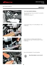
Page 67: ...injector Remove the fuel injector D from its fuel line E Repeat the procedure in reverse to refit Replace the O rings F every time you remove the fuel injector 15 10 REMOVING THE ELECTRONIC INJECTION...

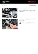
Page 68: ...A and the TPS s connector B Loosen the metal clamps C Pull the throttle cable pin D out of the fitting E on the throttle body Fully unscrew the nut F fastening the throttle cable Release the throttle...

Page 69: ...L TL 250 ELECTRICAL DEVICES 15 10 3 Removing the MAP sensor Remove the screw A and release the MAP sensor from its slot on the engine Disconnect the connector B and the retaining bracket C from the MA...

Page 70: ...orrelation P0080 Exhaust valve control solenoid circuit high Bank 1 P0081 Suction valve control solenoid valve bank 2 P0082 Low voltage of the suction valve control solenoid valve circuit bank 2 P0083...

Page 71: ...elow thermostat regulating temperature P0129 Barometric pressure too low P0130 Oxygen sensor heating circuit bank 1 sensor 1 ERROR CODE ERROR P0084 Exhaust valve control solenoid valve bank 2 P0085 Ex...

Page 72: ...r 1 P0134 Oxygen sensor P0135 Oxygen sensor heating circuit bank 1 sensor 1 P0136 Oxygen sensor heating circuit bank 1 sensor 2 P0137 Heated oxygen sensor heater control circuit bank 1 sensor 2 low P0...

Page 73: ...balancing Fuel trim at min limit P02A8 Cylinder 4 balancing Injector restricted P02A9 Cylinder 4 balancing Injector leaking P02AA Cylinder 5 balancing Fuel trim at max limit ERROR CODE ERROR P020C In...

Page 74: ...position sensor B circuit bank 1 P0366 Camshaft Position Sensor B Circuit Range Performance bank 1 P0367 Camshaft Position Sensor B Circuit Low Input Bank 1 P0368 Camshaft Position Sensor B Circuit H...

Page 75: ...aporative emissions purge valve range performance P0467 Evaporative emissions purge valve signal too low ERROR CODE ERROR P0370 Timing Reference High Resolution Signal A P0371 Timing Reference High Re...

Page 76: ...ntake Air Heater A Circuit high P0543 Intake Air Heater A Circuit Open ERROR CODE ERROR P0468 Evaporative emissions purge valve signal too high P0469 Evaporative emissions purge valve intermittent P04...

Page 77: ...625 Generator Field F Terminal Circuit Low P0626 Generator Field F Terminal Circuit High P0627 Fuel Pump A Control Circuit Open ERROR CODE ERROR P0547 Exhaust Gas Temperature Sensor Circuit bank 2 sen...

Page 78: ...Reference Voltage D Circuit Open P06A4 Sensor Reference Voltage D Circuit Low P06A5 Sensor Reference Voltage D Circuit High P06A6 Sensor Reference Voltage A Circuit Range Performance ERROR CODE ERROR...

Page 79: ...Reference Voltage C Circuit Range Performance P06A9 Sensor Reference Voltage D Circuit Range Performance P06AF Torque Management System Forced Engine Shutdown P06B0 Sensor Power Supply A Circuit Open...

Page 80: ...w P0931 Gear Shift Lock Solenoid Circuit High P0932 Hydraulic pressure sensor circuit P0933 Hydraulic pressure sensor range performance P0934 Hydraulic pressure sensor circuit low input P0935 Hydrauli...

Page 81: ...rent P0A77 Alternator Phase W High current P0A7A Alternator inverter performance P0A7B Battery Energy Control Module Requested MIL Illumination P0A7C Motor Electronics Over Temperature P0A80 Replace H...

Page 82: ...0B8 Reductant Metering Unit Heater Control Circuit High P20B9 Reductant Heater A Control Circuit Open P20BA Reductant Heater A Control Circuit Performance P20BB Reductant Heater A Control Circuit Low...

Page 83: ...F Circuit Low P2133 Throttle Pedal Position Sensor Switch F Circuit Intermittent P2134 Throttle Pedal Position Sensor Switch A B Voltage Correlation P2135 Throttle Pedal Position Sensor Switch A C Vol...

Page 84: ...3 P2234 Heated oxygen sensor heater HO2S Bank 2 Sensor 1 ERROR CODE ERROR P2138 Throttle Pedal Position Sensor Switch D E Voltage Correlation P2139 Throttle Pedal Position Sensor Switch D F Voltage C...

Page 85: ...on Coil I Secondary Circuit P2327 Ignition Coil J Primary Control Circuit Low ERROR CODE ERROR P2235 Heated oxygen sensor heater HO2S Bank 2 Sensor 2 P2236 Heated oxygen sensor heater HO2S Bank 2 Sens...

Page 86: ...ft P2592 Cruise Control Front Distance Range Sensor Right P2600 Coolant Pump A Control Circuit Open P2601 Coolant Pump A Control Circuit Range Performance P2602 Coolant Pump A Control Circuit Low ERRO...

Page 87: ...uit Low P267A B Rocker Arm Actuator Position Sensor Circuit Bank 2 P267B B Rocker Arm Actuator Position Sensor Circuit Range Performance Bank 2 P267C B Rocker Arm Actuator Position Sensor Circuit Low...

Page 88: ...essure Control Solenoid Control Circuit Stuck On P2759 Torque Converter Clutch Pressure Control Solenoid Control Circuit Electrical P2760 Torque Converter Clutch Pressure Control Solenoid Control Circ...

Page 89: ...xhaust valve control circuit high P3417 Cylinder 3 Deactivation Intake Valve Control Circuit Open P3418 Cylinder 3 Deactivation Intake Valve Control Circuit Performance P3419 Cylinder 3 Deactivation I...

Page 90: ...ction C1042 Front wheel speed sensor Not plausible C1043 Front wheel speed sensor Short circuit to ground C1044 Rear wheel speed sensor Not plausible C1045 Rear wheel speed sensor Short circuit to gro...

Page 91: ...sible C1DAA Rear wheel pressure sensor circuit C1DD3 ECU software error C1DF0 Recirculation pump C1DF1 Recirculation pump C1DF2 Generic hardware error inside the control unit C1DF4 Low electric voltag...

Page 92: ...fuel level adjustment Choke jet clogged Air leaking in Automatic choke Atomizer malfunctioning Ignition unit malfunctioning Thermal cutout malfunctioning Air filter Air filter dirty Air filter not pos...

Page 93: ...alves leaking Poor valve and valve seat contact Incorrect valve timing Valve spring broken Valve seized IDLING MALFUNCTIONING Carburettor Slow jet loose or clogged Carburettor coupler damaged Carburet...

Page 94: ...ogged Air filter dirty Jet clogged Incorrect fuel level adjustment Incorrect carburettor air line adjustment Air filter Filter dirty Compression system Cylinder worn Piston ring worn or stuck Cylinder...

Page 95: ...ustment Engine oil Incorrect oil level Unsuitable oil quality high viscosity Poor oil quality Brakes Brakes jammed Cooling system Thermostat faulty Thermal cutout faulty Incorrect coolant level low Ra...

Page 96: ...logged damaged Radiator cap faulty Impeller shaft deformed Fan motor disconnected 16 6 STEERING INSTABILITY Product Specific Area Involved Cause STEERING INSTABILITY Handlebars Mounting screw loose St...

Page 97: ...ken Engine Engine seized 16 8 FAULTY INDICATOR SYSTEM AND LIGHTING 16 8 1 DIM HEADLIGHT Unsuitable bulb Too many electrical accessories Trouble charging Rectifier regulator faulty Battery faulty Elect...

Page 98: ...ATORS FLASHING TOO SLOW Direction indicator relay faulty Insufficient battery capacity almost dead Unsuitable bulb ON OFF switch and or direction indicator switch faulty 16 8 6 DIRECTION INDICATORS FL...

Page 99: ...in lubricant Spray on drive chain grease Brake oil Brake fluid DOT 4 or 5 1 Electric contact cleaner Contact cleaner Fuel 95 or 98 premium unleaded petrol Paste for sealing engine covers on crankcase...

Page 100: ...wo cooling system hoses C Remove the engine earthing cable D Remove the air hose A and clutch cable B 18 1 REMOVING THE ENGINE FULLY Place the vehicle on a central stand and support the weight at the...

Page 101: ...101 101 CHAPTER 18 ENGINE WORKSHOP MANUAL TL 250 Remove the starter motor wire F Remove the neutral sensor E Disconnect the pick up and alternator connectors G and H Remove the spark plug boot I...

Page 102: ...g 20 ft lb Repeat the procedure in reverse to refit 18 2 CHANGING ENGINE OIL AND ENGINE OIL FILTERS Stand the motorcycle perfectly upright Remove the M16 oil drain bolt A from the bottom of the engine...

Page 103: ...viously removed parts in the order you took them out Install the filter with the black plastic facing in Measure 1500 1600 ml of oil with the measuring cup and fill the engine through the filler openi...

Page 104: ...sides respectively Remove the two M6 60 bolts two M6 35 bolts and four M6 30 bolts from the cylinder head cover Remove the cylinder head cover 18 4 2 Remove the cylinder head Remove the cylinder head...

Page 105: ...der head cover disassembly Remove the two M14 1 bolts from the locating plate on the rocker arm shaft on the cylinder head cover Remove the intake and exhaust rocker arm shaft and intake and exhaust r...

Page 106: ...corrosion and there is poor valve seating it is hard to get the desired seal and you will need to install a new valve Measure the valve spring s free length 48 35 mm Service limit value Spring 47 5 m...

Page 107: ...valve seat for cracks Check the cylinder for warp and measure the flatness of the cylinder head using a straight edge and a feeler gauge 18 4 9 Inspect and lap the valve seat Clean the combustion cha...

Page 108: ...head 18 4 12 Assemble the cylinder head Fitthelowervalvespringseatandtheoilpanonthevalveguide Insert the intake and exhaust valve stem applying lubricant inside the valve guide Fit the valve spring u...

Page 109: ...head cover has been fitted turn the rocker arm The rocker arm must be able to turn freely without requiring any effort Torque setting Rocker arm shaft setting plate bolts 16 20 Nm 1 6 2 kgf m 11 8 14...

Page 110: ...the mark G and the mating surface are on the same plane Timing is only correct once the conditions in points 2 and 3 are met Install the tensioner on the cylinder block by inserting it in the relevan...

Page 111: ...nd adjusting tappets With the engine cold on the left hand side of the engine remove caps A and B from the ignition cover caps C and D from the tappet cover covers E on the head and the spark plug Ins...

Page 112: ...performing this job 18 5 2 Inspect the cylinder block Check the cylinder block for wear or damage Measure the cylinder s inside diameter at three separate points namely at the top in the middle and a...

Page 113: ...2nd ring 0 08 mm Oil ring 0 08 mm Checkthepistonforwearorcracksandchecktheseatforwear Install the ring on the cylinder Service limit value Top ring 0 5 mm 2nd ring 0 5 mm Oil ring 1 4 mm Measure the i...

Page 114: ...ings Install the top and 2nd piston rings with the markings facing the piston head The piston rings should be able to turn freely once installed The gap in the oil ring should line up correctly with t...

Page 115: ...mpeller Remove the drain bolt from the pump cover drain the refrigerant via the bolt and remove the pump cover and impeller until water stops coming out 18 5 9 Remove the crankcase cover on the engine...

Page 116: ...gether with the actual gear when you remove the gear assembly and be very careful with the washer 18 5 13 Remove the oil pump on the right side Remove the oil pump s intermediate gear and the oil pump...

Page 117: ...for damage If the gasket is damaged replace it Check the oil seal on the clutch cover on the outer end of the crankshaft where necessary replace the oil seal with a new one with the marking facing ou...

Page 118: ...l system keep the outer side marking facing in Apply a little silicone lubricating grease to the water seal system s main lip Press and insert a new water pump shaft using the special tool Insert the...

Page 119: ...isc Service limit value 2 85 mm Check the surface of the clutch disc for warp Use a feeler gauge for inspection Service limit value 0 14 mm Check clearance between the clutch basket and clutch disc Se...

Page 120: ...ts for wear or damage 18 5 25 Inspect the primary starter gear Check the primary starter gear for wear or damage 18 5 26 Inspect the oil pump on the right side of the engine case Check the oil pump s...

Page 121: ...the right side of the engine case Insert the oil pump pin in the relevant hole in the pump shaft Insert the rotor assembly in the opening in the right side of the engine case and secure the oil pump c...

Page 122: ...e in the mainshaft Next insert the clutch push rod into the central hole in the mainshaft before inserting the thrust bearing and washer on the push rod Fit the clutch pressure plate relevant spring s...

Page 123: ...the generator rotor Remove the lock nut from the magnet rotor and remove the rotor using the special tool You must only use the special tool to remove the rotor Do not hammer the rotor If the magnet i...

Page 124: ...over on the left side Check the balancer shaft oil gasket on the left side crankcase cover for damage If there is any issue replace it 18 6 7 Inspect the generator rotor and stator Check the magnet st...

Page 125: ...ng the balancer shaft driven gear onto the actual balancer shaft Slide the balancer drive gear onto the left end of the crankshaft before sliding the crankshaft gear onto the left end of the crankshaf...

Page 126: ...e sure you do not miss any of the mainshaft assembly and countershaft assembly components 18 7 3 Inspect the crankshaft Set the crankshaft on a pair of V blocks Using a dial gauge measure the cranksha...

Page 127: ...bearings on the crankcase left and right sides for slow rotationand ifthisisthecase installnewbearingsofthesametype Remove the bearings from the crankcase to check eccentricity and ensure they rotate...

Page 128: ...mm Countershaft fork shaft service limit value 13 95 mm Measure the thickness of the ends Service limit value 4 7 mm Check the shift drum surface and slots for wear or damage 18 7 6 Inspect the mains...

Page 129: ...the fork marked R on the countershaft on the right side the fork marked L on the countershaft on the left side and the fork marked C on the mainshaft Fit the shift drum into the relevant openings in t...

Page 130: ...e opening facing the crankcase s left side Install the filter cap on the pin and secure in place by tightening the two M5 nuts Torque setting Engine oil filter cap nuts 7 to 9 Nm Insert the oil filter...

Page 131: ...go in for its first service within its first year of use even if it has not completed the stated 1 000 km 600 mi The vehicle must go in for a further checkup within its second year of use even if it h...

Page 132: ...tension alignment and condition Inspect and check the front and rear sprockets Adjust and lubricate the drive chain fully with a specific chain lubricant Every 500 km 300 mi Following heavy use Replac...

Page 133: ...for oil leaks Every 1 000 km 600 mi Change Engine oil filter Replace Cooling system Check the coolant level and inspect the vehicle for coolant leaks Change the coolant Every 3 years Front brake and r...

Page 134: ...ion and lubrication every 500 km 321 mi Front and rear brake pad wear every 2000 km 1250 mi Nut and bolt tightness Coolant every 2000 km 1250 mi Rear shock absorber Carburettor Clutch cables and contr...

Page 135: ...ery 2000 km 1250 mi or 12 months Every 5000 km 3125 mi or 12 months Braking systems Brake fluid every 2 years Valve clearance Exhaust silencer Engine oil and oil filter Fork oil and oil seal every 120...

Page 136: ...136 136 WORKSHOP MANUAL TL 250...

Page 137: ...URER S DATA AND EDITION Fantic Motor SPA Via Tarantelli 7 31030 Dosson di Casier TV Italy Tel 39 0422 634192 Fax 39 0422 1830124 Email info fanticmotor it www fanticmotor it Edition 01 2019 WORKSHOP M...

Page 138: ...FANTIC MOTOR S P A Fantic Motor SPA Via Tarantelli 7 31030 Dosson di Casier TV Italy info fanticmotor it www fanticmotor it...

Reviews: