25
WORKSHOP MANUAL
TL 250
CHAPTER 6
DASHBOARD
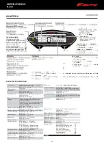
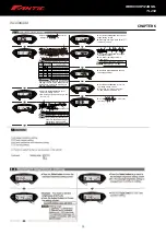
Indication light
Neutral (green light)
Right indication light (green light)
Water temperature (red light)
Motor oil (red light)
Engine (yellow light)
Left indication light (green light)
Fuel (yellow light)
High beam light (blue light)
l
l
o
l a ning
etting range
when lower than (including)
etting alue fuel le el
ymbol will blin
otal ngin o
ating ti
i play range
hour
i play unit
hour
ngin o
ating ti
i play range
hour
i play unit
hour
d u t
elect
Int
nal
i play range
m (mile)
u er unad u table
i play unit
m (mile)
t
nal
etting range
m (mile)
etting unit m (mile)
loc o
at
etting range
hr format
hr format
loc
etting range
:
:
(
hr format)
:
:
(
hr format)
oto oil aint nanc illag
i play range
unit
(
m u er ad u table)
m automatic decrea e according to the increa e of total millage
i play range nch
(
mile u er ad u table)
mile automatic decrea e according to the increa e of total millage
i play unit m (mile)
Speedometer
●Display range :
0 ~ 360 km/h (0 ~ 225 mile)
Maximum speed record
●Display range : 0 ~ 360 km/h (0 ~ 225 mile)
Maximum RPM record
●Display range : 0 ~ 15,000 RPM
Odometer
●Display range : 0 ~ 99999.9 km (mile),
return to zero upon exceed.
●Display unit : 0.1 km (mile)
Trip meter A
、
B
●Display range : 0 ~ 999.9 km (mile),
return to zero upon exceed.
●Display unit : 0.1 km (mile)
Tachometer
●Display range : 0 ~ 15,000 RPM
●Display unit : 10 RPM
Voltmeter
●Display range : DC 8.0 V ~ 16.0 V
●Display unit : 0.1 V
3-1
Basic function instruction
3-2
Function, setting instructions
MOTO / SCOOTER
MOTO / SCOOTER
spe ed
sensor
below
8
m m
EX. 4 Rear disc - detect the gap between the disc.
Install the s type sensor bracket.
Adjust the sensor bracket position to make
sure that the sensor could face the magnet
to prevent bad speed signal or no signal!
Install the speed sensor on the bracket.
Adjust the distance between sensor and
magnet. We suggest you to make sure the
distance is under
for catching good
speed signal.
1 mm
S type speed sensor bracket instruction
L type speed sensor bracket instruction
Please install the L bracket and the anti-slip
rubber on the front fork and adjust it to the
proper height and angle.
Please use the cable tie to fix the bracket on
the front fork. Please make sure the disc
screw could pass the hole on the bracket for
you to install the sensor into the same hole for
catching the speed signal.
Install the speed sensor on the bracket.
Adjust the distance between sensor and
magnet. We suggest you to make sure the
distance is under
for catching good
speed signal.
1 mm
After installation, please use your hand to turn the tire to see is everything ok. The LED on the active speed sensor will light up once
the signal is detected.
EX. 1
The active speed sensor could be installed by the metal parts to detect the speed.
EX. 1 The disc screw.
EX. 2 The disc to detect the disc gap. (Please make sure the distances between the gaps are the same in advance to avoid wrong
speed signal.)
EX. 3 The sprocket to detect the disc gap. (Please make sure the distances between the gaps are the same in advance to avoid wrong
speed signal.)
We will suggest you to catch the speed from the disc screws. The more the sensor points are, the better the speed accuracy is. The
maximum sensor points the speed sensor could detect is 20 points per turn.
speed
sensor
speed
sensor
the detect range
speed
sensor
speed
sensor
speed
sensor
the detect range
speed sensor
speed sensor
the detect range
speed sensor
speed sensor
the detect range
EX. 2
、
4
EX. 3
The hexagon socket disc screw
The best detect area: The edge of
the hexagon socket screw.
Please don't catch the signal from
the middle hole of the hexagon
socket screw to avoid wrong signal.
The hexagon screw
The best detect area: The middle
of the screws.
Some hexagon screw center is with a small
hole in the center in this case,we will suggest
you to catch the signal from the edge of the
screw like the hexagon socket screw.
The disc
The best detect area: Please detect
the speed signal from the gaps of the disc.
Please note that there are discs with
the gaps in different difference, and
this method will not work on it!
The sprocket
The best detect area: Please detect the
speed signal from the gaps of the sprocket.
Please note that there are sprockets
with the gaps in different difference,
and this method will not work on it!
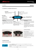
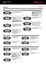
Indication light
●Neutral (green light)
●
●
Right indication light (green light)
Water temperature (red light)
●
●
Motor oil (red light)
Engine (yellow light)
●
Left indication light (green light)
●
Fuel (yellow light)
●High beam light (blue light)
Average speed record
●Recording range :
0 ~ 360 km/h (0 ~ 225 MPH)
Tachometer
●Display range : 0 ~ 10,000 RPM
、
0 ~ 12,000 RPM
、
0 ~ 15,000 RPM
Fuel Level
●Setting range : 100Ω
、
250Ω
、
270Ω
、
510Ω
、
1200Ω
、
SWITCH
、
USER
Low fuel warning
●Setting range : 10 ~ 50%,
when lower than (including)
setting value, fuel level
symbol will blink.
Total engine operating time
●
●
Display range : 0~99,999.9 hours
Display unit : 0.1 hour
Engine operating time A,B
●
●
Display range : 0~9,999.9 hours
Display unit : 0.1 hour
Adjust
Select
Internal ODO
●
●
Display range : 0 ~ 99,999.9 km (mile) ,
user unadjustable.
Display unit : 0.1 km (mile)
External ODO
●
●
Setting range : 0 ~ 99,999 km (mile)
Setting unit : 1 km (mile)
●
Clock format
●Setting range : 12 - hrs format, 24 - hrs format.
Clock
Setting range : 0
:
00 ~ 23
:
59 (24 - hrs format),
1
:
00 ~ 12
:
59 (12 - hrs format)
●
●
●
Motor oil maintenance millage
Display range : SI unit :
500 (~ 8,000 km, user adjustable) ~ -999 km, automatic decrease according to the increase of total millage.
Display range : Inch :
300 (~5,000 mile user adjustable)~ -999 mile, automatic decrease according to the increase of total millage.
Display unit : 1 km (mile)
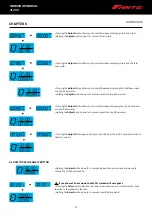
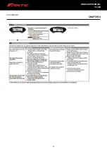
● Speedometer
Display range : 0 ~ 360 km/h (0 ~ 225 MPH)
Will blink when exceed range.
Display unit : 1 km (mile)
○
Display internal
○
Trip meter A
、
B
○
Odometer
<0.5 second
Display range : 0 ~ 99,999.9 km (mile), return
to zero upon exceed.
Display unit : 0.1km (mile)
Display range : 0 ~ 999.9 km (mile), return to
zero upon exceed.
Display unit : 0.1km (mile)
○
Maximum speed recordDisplay range : 0 ~360 km (0 ~ 225 mile)
Display unit : 1 km (mile)
○
Average speed recordRecording range : 0 ~ 360km/h (0 ~ 225 MPH)
○
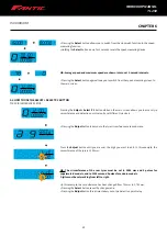
Tire circumference
Setting range : 300 ~ 2,500 mm
Setting unit : 1 mm
○
Sensitive point
Setting range : 1 ~ 20 points
Setting range : 1 point
○
The RPM input signal number setting
Setting range : P-0.5,P-1~P-25
○
The RPM input pulse Setting range : lo-Act, Hi-Act
○
Display internal
<0.5 second
●
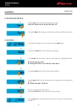
Tachometer
Display range : 0 ~ 15,000 RPM
Display unit : 10 RPM
○
Stage tachometer
Display range : 0 ~ 10,000 RPM
、
0 ~ 12,000 RPM
、
0 ~ 15000 RPM
Display unit :
0 ~ 10,000 RPM (333 RPM each stage)
0 ~ 12,000 RPM (400 RPM each stage)
0 ~ 15,000 RPM (500 RPM each stage)
○
MAX RPM record
Display range : 0 ~ 15,000 RPM
Display unit : 10 RPM
●
Total hour meter
Display range :0 ~ 99,999.9 hour
Display unit : 0.1 hour
○
Display range :0 ~ 9,999.9 hour
Hour meter A
、
B
Display unit : 0.1 hour
●
Motor oil maintenance
millage
●
Fuel level
Setting range : 100Ω
、
250Ω,
、
270Ω
、
510Ω
、
1200Ω
、
SWITCH
、
USER
○
Staged fuel gauge
○
Digital fuel gauge
Setting range : 0 ~ 100 %
●
External ODO
Setting range : 0~99999 km (mile)
Setting unit :1km (mile)
●
Effective voltage
●
Effective temperature range
●
Meter weight
●
Meter size
●
Meter standard
120 x 46 x 20 mm
Around 240 g
DC 12 V
JIS D 0203 (S2)
-10 ~ +60 °C
●
Backlight color
Display range: white
Setting unit : 1 hour
●
Clock format
Setting range : 12-hrs format, 24-hrs format
○
Setting range : 0 ~ 23 (24-hrs format),
1 ~ 12 (12-hrs format)
Clock (hours)
○
Clock (minute)
Setting range : 00:59 minutes
Display range : 1 minute
●
Volt meter
Display range : DC8.0 V ~ 16.0 V
Display unit : 0.1V
●
Internal ODO
Display range : 0~99999.9 km (mile), user
unadjustable
Display unit : 0.1 km (mile)
●
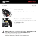
Indicator light
Neutral (green light)
Right indication light (green light)
Water temperature (red light)
Motor oil (red light)
High beam light (blue light)
Left indication light (green light)
Fuel (yellow light)
Engine (yellow light)
Setting unit : 10 %
○
Low fuel warning
Setting range : 10 ~ 50 %, when lower than
(including) setting value, fuel level symbol will blink.
Setting unit : 10%
Display range : SI unit : 500 (~8000 km, user adjustable)
~ -999 km, automatic decrease according to the
increase of total millage.
Display range : Inch : 300 (~ 5000 mile user adjustable)
~ -999 km, automatic decrease according to the
increase of total millage.
Display unit : 1 km (mile)
Setting range : 10 stage display
Warning range : Fuel level warning stage below
(including) setting value, fuel level symbol will blink.
NOTE
Any design and specification changes will not be notify.
wh041ba02a(P6-2)
BASIC FUNCTION INSTRUCTION
Summary of Contents for TL 250
Page 1: ...1 WORKSHOP MANUAL E N...
Page 3: ...WORKSHOP MANUAL TL 250...
Page 11: ...11 WORKSHOP MANUAL TL 250...
Page 30: ...30 WORKSHOP MANUAL TL 250 CHAPTER 6 DASHBOARD 39 GENERAL CONTENT AND CONSULTATION ENGLISH...
Page 49: ...49 49 WORKSHOP MANUAL TL 250...
Page 51: ...51 CHAPTER 15 ELECTRICAL DEVICES 51 WORKSHOP MANUAL TL 250...
Page 136: ...136 136 WORKSHOP MANUAL TL 250...


