


I
Table of Contents
Parts Description ............................................................................... 1
System Disassembly ......................................................................... 9
Detach the Optional Peripherals .............................................................. 10
Disconnect the Modular MSR/i-Button Module ............................................... 10
Disconnect the Modular VFD Customer Display ............................................. 11
Detach the Base from POS Unit ............................................................... 12
Disassemble the POS Unit ....................................................................... 13
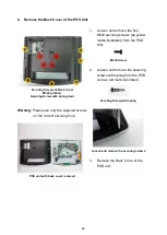
Remove the Back Cover of the POS Unit ....................................................... 14
Remove the I/O Board of Modular MSR/i-Button ............................................ 16
Disconnect the Touch Control Unit (Capacitive Type) ..................................... 18
Disconnect the Touch Control Unit (Resistive Type) ....................................... 19
Disconnect the LVDS Cable from the Main Board .......................................... 20
Disconnect the Inverter Cable from the Main Board ....................................... 20
Disconnect the Connectors of Speakers & Power Indicator ........................... 21
Remove the CPU Fan & Heat Sink (for POS-6000-I only) .............................. 24
Remove the Speaker and Power Switch ........................................................ 25
Detach the LCD Panel from Chassis .............................................................. 27
Remove the Power Indicator from the Front Bezel Set ................................... 28
Remove the LED Back light Board (for Front Bezel Set with TYSSO LOGO
Disassemble the Base Kit ........................................................................ 30
Remove the Power Adapter and Base ........................................................... 30


