background image

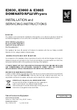
E421/E421F

E422/E422F FRYERS

INSTALLATION, SERVICING 
and USER INSTRUCTIONS

IMPORTANT

The installer must ensure that the installation of the appliance is in conformity with these instructions
and National Regulations in force at the time of installation. 

Particular attention MUST be paid to -

BS7671 IEE Wiring Regulations

Electricity at Work Regulations

Health And Safety At Work Act

Fire Precautions Act

This appliance has been CE-marked on the basis of compliance with the Low Voltage and EMC
directives for the voltages stated on the data plate.

WARNING -THIS APPLIANCE MUST BE EARTHED

On completion of the installation these instructions should be left with the Engineer-in-Charge for
reference during servicing. Further to this, The Users Instructions should be handed over to the User,
having had a demonstration of the operation and cleaning of the appliance.

IT IS MOST IMPORTANT THAT THESE INSTRUCTIONS BE CONSULTED BEFORE INSTALLING
AND COMMISSIONING THIS APPLIANCE. FAILURE TO COMPLY WITH THE SPECIFIED
PROCEDURES MAY RESULT IN DAMAGE OR THE NEED FOR A SERVICE CALL.

PREVENTATIVE MAINTENANCE CONTRACT

In order to obtain maximum performance from this unit we would recommend that a Maintenance
Contract be arranged with SERVICELINE. Visits may then be made at agreed intervals to carry out
adjustments and repairs. A quotation will be given upon request to the SERVICELINE contact
numbers below.

WEEE Directive Registration No. WEE/DC0059TT/PRO

At end of unit life, dispose of appliance and any replacement parts in a safe manner, via
a licenced waste handler. Units are designed to be dismantled easily and recycling of all 
material is encouraged whenever practicable.

Falcon Foodservice Equipment

HEAD OFFICE AND WORKS

Wallace View, Hillfoots Road, Stirling. FK9 5PY. Scotland.

SERVICELINE CONTACT

Phone: 01438 363 000

Fax: 01438 369 900

T100798 Ref. 6

Summary of Contents for E421

Page 1: ...peration and cleaning of the appliance IT IS MOST IMPORTANT THAT THESE INSTRUCTIONS BE CONSULTED BEFORE INSTALLING AND COMMISSIONING THIS APPLIANCE FAILURE TO COMPLY WITH THE SPECIFIED PROCEDURES MAY...

Page 2: ...n systems Gas water and electrical supply external to unit Light bulbs Re installing vacuum in kettle jackets Replacement of grill burner ceramics when damage has been clearly caused by misuse Where a...

Page 3: ...MODEL NUMBERS NETT WEIGHTS and DIMENSIONS 1 2 SITING The unit must be installed on a firm level floor in a well lit draught free position The fryer should not be installed in a position where the poss...

Page 4: ...r 4 Heat Demand Indicator Amber illuminates when elements are on Goes out when desired temperature is reached 2 3 2 E422F Fryer Control Panel See Figure 3 Figure 3 E422F Control Panel 1 Four Digit LED...

Page 5: ...e manner Emphasis should be given to safe operation and use of drain valve and oil bucket Oil bucket should not be overfilled to allow safe movement Oil should be allowed to cool before any manual han...

Page 6: ...RS a Remove control panel by undoing fixings at top and bottom Unplug control panel b Disconnect electrics loom and remove fixings to enable controller to be removed c Carefully replace in reverse ord...

Page 7: ...SECTION 5 CRITICAL DIMENSIONS 7 8 10 Wu Set to 0 8 Set to 10 minutes Set to Wu Timer Pump Settings Set for 230V...

Page 8: ...um Hot Fill Mark See Figure 6 Medium and Foodstuffs As foodstuffs increase volume within fry pot follow these rules NEVER ADD WATER TO FRYER MEDIUM WARNING No attempt must be made to operate appliance...

Page 9: ...sing the following guide in Section 6 3 2 Operating the Controller a To start a timing cycle Press any product key 1 to 4 to start a timing cycle If key is programmed correct time will display and wil...

Page 10: ...mming a Product Cycle Time and Action Alarm a Press and hold P key for 3 seconds Prog will be displayed Note Programming mode will exit automatically if no keys are pressed within 2 minutes b Select a...

Page 11: ...ION 8 CLEANING and MAINTENANCE RECOMMENDATION Personal protective equipment PPE s should be used when cleaning or handling medium within this appliance WARNING NEVER PUMP WATER THROUGH THE FILTRATION...

Page 12: ...top quality medium to obtain optimum results Shortening or solid fats can be used if necessary Solid fats MUST be heated carefully Solid fat has a lower smoke point temperature than shortening E421F f...

Page 13: ...ne whilst oil is below 180 C 5 It is advised that a skimmer is used continuously between frying batches of food to remove any floating debris Failure to do this may result in oil becoming bitter to ta...

Page 14: ...183 BW49183 PROBE PROBE ON OFF SWITCHES ON OFF SWITCHES 42 42 14 14 23 23 26 26 2A 2A A S FUSE A S FUSE 45 45 30 30 33 33 27 27 9 WAY MALE PLUG HOUSING 9 WAY MALE PLUG HOUSING MATE WITH CONTROL PANEL...

Page 15: ...91 90 90 104 104 103 103 102 102 21 21 NEUTRAL TERMINALS NEUTRAL TERMINALS 29 29 23 23 26 26 2A A S FUSE 2A A S FUSE 30 30 33 33 27 27 9 WAY MALE 9 WAY MALE PLUG HOUSING PLUG HOUSING MATE WITH MATE WI...

Page 16: ...LOOM BW49183 BW49183 92 92 91 91 90 90 104 104 103 103 102 102 ON OFF SWITCHES ON OFF SWITCHES 28 28 25 25 5A A S FUSE 5A A S FUSE 23 23 26 26 2A A S FUSE 2A A S FUSE 45 45 28 28 36 36 B B B A A 4 5 6...

Page 17: ...TO CONTROL PANEL WIRING LOOM WIRING LOOM BW49271 BW49271 PROBE PROBE ON OFF SWITCHES ON OFF SWITCHES 61 61 TRANSFORMER TRANSFORMER 22 22 16 16 28 28 25 25 5A A S FUSE 5A A S FUSE 2A A S FUSE 2A A S FU...

Page 18: ...577 86 87 88 90 FIT TO ELEMENT BOX 9 WAY FEMALE PLUG HOUSING 1 2 3 4 5 6 7 8 9 96 95 110 LEFT AMBER RV100 107 87 FIT TO TERMINAL BLOCK CONNECTOR IN ELEMENT BOX 9 WAY FEMALE PLUG HOUSING 9 8 7 6 5 4 3...

Page 19: ...100 100 99 83 93 95 91 92 83 93 95 96 96 7 6 8 9 1 3 2 4 5 OPERATES RH SIDE ELEMENT FROM TRANSFORMER ON MAIN LOOM 64 64 FIT TO TERMINAL BLOCK CONNECTOR IN ELEMENT BOX 4 WAY CRIMP TERMINAL HOUSING 103...

Page 20: ...TOR PROBE THERMISTOR PROBE 13 15 17 22 37 53 7 9 11 5 3 1 45 46 2 4 6 48 47 32 31 14 16 18 40 39 8 10 12 20 24 23 29 30 96 93 86 84 83 91 92 101 27 100 26 95 98 99 33 81 82 97 102 103 C5 C5 C9 C6 C6 G...

Page 21: ...2 91 83 84 86 93 96 30 29 23 24 20 12 10 8 39 40 18 16 14 31 32 47 48 6 4 2 46 45 1 3 5 11 9 7 53 37 22 17 15 13 THERMISTOR PROBE THERMISTOR PROBE ON OFF SWITCH 1 2A FUSE 2A FUSE OPERATING POWER SWITC...

Page 22: ...USE 2A FUSE ON OFF SWITCH 1 THERMISTOR PROBE 13 15 17 22 37 53 7 9 11 5 3 1 45 46 2 4 6 48 47 32 31 14 16 18 40 39 8 10 12 20 24 23 71 96 93 91 92 33 27 100 26 95 82 101 99 102 103 C5 C5 CTT CONTROLLE...

Page 23: ...12 10 8 39 40 18 16 14 31 32 47 48 6 4 2 46 45 1 3 5 11 9 7 53 37 22 17 15 13 THERMISTOR PROBE THERMISTOR PROBE ON OFF SWITCH 1 2A FUSE 2A FUSE OPERATING POWER SWITCH A1 A2 CTT CONTROLLER SAFETY STAT...

Page 24: ...24...

Reviews: