background image

8|60 - 

BCSD 

CAN

B

eta series 

C

ANopen

 S

ervo 

D

rives | Ref.2102

Installation manual

1.1. System Configurations

The following tables show the possible system configurations; in other words, the various
motors and drives available with their corresponding cables:

FS5 spindle motors

MOTOR MODEL

SPINDLE COMPACT DRIVE MODEL

400 Vac

FS5-A037-S5C0-A

SCD 1.25

FAGOR S5 motor, 400 Vac, 
PS1/PS6-40%: 3.7/5.5 kW, 
Incremental TTL encoder, 1024 P/R, 
Keyless.

FS5-A037-S5C1-A

SCD 1.25

FAGOR S5 motor, 400 Vac, 
PS1/PS6-40%: 3.7/5.5 kW, 
Incremental TTL encoder, 1024 P/R, 
With key.

FS5-A055-S5C0-A

SCD 1.25

FAGOR S5 motor, 400 Vac, 
PS1/PS6-40%: 5.5/7.7 kW, 
Incremental TTL encoder, 1024 P/R, 
Keyless.

FS5-A055-S5C1-A

SCD 1.25

FAGOR S5 motor, 400 Vac, 
PS1/PS6-40%: 5.5/7.7 kW, 
Incremental TTL encoder, 1024 P/R, 
With key.

FS5-A075-S5C0-A

SCD 2.35

FAGOR S5 motor, 400 Vac, 
PS1/PS6-40%: 7.5/11.0 kW, 
Incremental TTL encoder, 1024 P/R, 
Keyless.

FS5-A075-S5C1-A

SCD 2.35

FAGOR S5 motor, 400 Vac, 
PS1/PS6-40%: 7.5/11.0 kW, 
Incremental TTL encoder, 1024 P/R, 
With key.

FS5-A110-S5C0-A

SCD 2.50

FAGOR S5 motor, 400 Vac, 
PS1/PS6-40%: 11.0/15.6 kW, 
Incremental TTL encoder, 1024 P/R, 
Keyless.

FS5-A110-S5C1-A

SCD 2.50

FAGOR S5 motor, 400 Vac, 
PS1/PS6-40%: 11.0/15.6 kW, 
Incremental TTL encoder, 1024 P/R, 
With key.

FS5-A150-S5C0-A

SCD 2.75

FAGOR S5 motor, 400 Vac, 
PS1/PS6-40%: 15.0/22.0 kW, 
Incremental TTL encoder, 1024 P/R, 
Keyless.

FS5-A150-S5C1-A

SCD-2.75

FAGOR S5 motor, 400 Vac, 
PS1/PS6-40%: 15.0/22.0 kW, 
Incremental TTL encoder, 1024 P/R, 
With key.

Summary of Contents for BCSD CAN

Page 1: ...DRIVE BCSD CAN Installation manual Ref 2102 ...

Page 2: ... validity of those applications Therefore except under the express permission from Fagor Automation any CNC application that is not described in the documentation must be considered as impossible In any case Fagor Automation shall not be held responsible for any personal injuries or physical damage caused or suffered by the CNC if it is used in any way other than as explained in the related docume...

Page 3: ...ram 24 3 2 SCD C0 Spindle Compact Drive Diagram 25 3 3 X Axis Diagram 26 3 4 Y Axis Diagram 27 3 5 Z Axis Diagram 28 3 6 Command Diagram 29 3 7 PLC I Os Diagram 30 4 CABLES 31 4 1 Connection between CNC and SCD Spindle Drive 32 4 2 Connection between CNC and BCSD Axis Drive 33 4 3 Connection between SCD C0 Spindle Drive and BCSD Axis Drive 34 4 4 Connection between BCSD 2 Axis Drive 35 4 5 Termina...

Page 4: ...4 60 BCSD CAN Beta series CANopen Servo Drives Ref 2102 Installation manual This page intentionally left blank ...

Page 5: ... l e d r i v e B C S D x D M G A x i s d r i v e F S 5 S p i n d l e m o t o r 3 p h 4 0 0 4 6 0 V a c M P C 4 x I E C D l X 4 C N 3 C N 4 C N 2 3 p h 3 8 0 4 4 0 V a c F B M x D L x x x C N 2 P C 3 p h 3 8 0 4 4 0 V a c C N 3 C N 4 C N 4 B S C T R B S C P C U S B 2 m C N 1 I O s C N 1 I O s F e e d a x i s m o t o r B C S D x D M G A x i s d r i v e C A N A X E S t e r m i n a l r e s i s t o r 5...

Page 6: ...L E N C O D E R X 4 B S C A A 3 0 0 m m B C S D x A M G A x i s d r i v e C N 3 C N 4 C N 2 3 p h 2 0 0 2 3 0 V a c C N 2 P C 3 p h 2 0 0 2 3 0 V a c C N 3 C N 4 C N 4 B S C T R C N 1 I O s C N 1 I O s B S C C A l 0 2 C A N A X E S B C S D x A M G A x i s d r i v e B S C P C U S B 2 m t e r m i n a l r e s i s t o r 5 1 0 1 5 m M P C F B S 1 8 l w i t h F B S 0 8 1 0 3 5 8 1 0 1 5 2 0 m E E C F B ...

Page 7: ...p h 2 0 0 2 3 0 V a c C N 2 P C 3 p h 2 0 0 2 3 0 V a c C N 3 C N 4 C N 4 B S C T R C N 1 I O s C N 1 I O s B S C C A l 0 2 C A N A X E S B C S D x A M G A x i s d r i v e F B M x A L x x x F e e d a x i s m o t o r B S C P C U S B 2 m t e r m i n a l r e s i s t o r 5 1 0 1 5 m M P C F B M 1 4 l 0 1 M P C F B M 1 2 l w i t h F B M 1 0 1 5 2 0 w i t h F B M 3 0 5 0 3 5 8 1 0 1 5 2 0 m E E C F B M ...

Page 8: ...l TTL encoder 1024 P R Keyless FS5 A055 S5C1 A SCD 1 25 FAGOR S5 motor 400 Vac PS1 PS6 40 5 5 7 7 kW Incremental TTL encoder 1024 P R With key FS5 A075 S5C0 A SCD 2 35 FAGOR S5 motor 400 Vac PS1 PS6 40 7 5 11 0 kW Incremental TTL encoder 1024 P R Keyless FS5 A075 S5C1 A SCD 2 35 FAGOR S5 motor 400 Vac PS1 PS6 40 7 5 11 0 kW Incremental TTL encoder 1024 P R With key FS5 A110 S5C0 A SCD 2 50 FAGOR S...

Page 9: ... Length m 5 10 15 20 30 40 50 75 100 150 200 250 300 MPC 4x4 M Motor power cable for FS5 075 S5C A motor Length m 5 10 15 20 30 40 50 75 100 150 200 250 300 MPC 4x6 M Motor power cable for FS5 110 S5C A motor Length m 5 10 15 20 30 40 50 75 100 150 200 250 300 MPC 4x10 M Motor power cable for FS5 150 S5C A motor Length m 5 10 15 20 30 40 50 75 100 150 200 250 300 ENCODER CABLE IECD Motor feedback ...

Page 10: ... key with oil seal and brakeless FBM 10ALB14 BCSD 10AMG FAGOR axis motor 200 Vac 1 kW 23 bit absolute serial encoder 8388608 P R SMT rotator without key with oil seal and holding brake FBM 10ALB22 BCSD 10AMG FAGOR axis motor 200 Vac 1 kW 23 bit absolute serial encoder 8388608 P R SMT rotator with key with oil seal and brakeless FBM 10ALB24 BCSD 10AMG FAGOR axis motor 200 Vac 1 kW 23 bit absolute s...

Page 11: ...Vac 1 5 kW 23 bit absolute serial encoder 8388608 P R SMT rotator with key with oil seal and holding brake MOTOR MODEL SERVO DRIVE MODEL MEDIUM INERTIA 400 Vac FBM 15DLB12 BCSD 15DMG FAGOR axis motor 400 Vac 1 5 kW 23 bit absolute serial encoder 8388608 P R SMT rotator without key with oil seal and brakeless FBM 15DLB14 BCSD 15DMG FAGOR axis motor 400 Vac 1 5 kW 23 bit absolute serial encoder 8388...

Page 12: ...Vac 2 0 kW 23 bit absolute serial encoder 8388608 P R SMT rotator with key with oil seal and holding brake MOTOR MODEL SERVO DRIVE MODEL MEDIUM INERTIA 400 Vac FBM 20DLB12 BCSD 20DMG FAGOR axis motor 400 Vac 2 0 kW 23 bit absolute serial encoder 8388608 P R SMT rotator without key with oil seal and brakeless FBM 20DLB14 BCSD 20DMG FAGOR axis motor 400 Vac 2 0 kW 23 bit absolute serial encoder 8388...

Page 13: ...c 3 0 kW 23 bit absolute serial encoder 8388608 P R Embedded rotator with key with oil seal and holding brake MOTOR MODEL SERVO DRIVE MODEL MEDIUM INERTIA 400 Vac FBM 30DLA12 BCSD 30DMG FAGOR axis motor 400 Vac 3 0 kW 23 bit absolute serial encoder 8388608 P R Embedded rotator without key with oil seal and brakeless FBM 30DLA14 BCSD 30DMG FAGOR axis motor 400 Vac 3 0 kW 23 bit absolute serial enco...

Page 14: ...c 5 0 kW 23 bit absolute serial encoder 8388608 P R Embedded rotator with key with oil seal and holding brake MOTOR MODEL SERVO DRIVE MODEL MEDIUM INERTIA 400 Vac FBM 50DLA12 BCSD 50DMG FAGOR axis motor 400 Vac 5 0 kW 23 bit absolute serial encoder 8388608 P R Embedded rotator without key with oil seal and brakeless FBM 50DLA14 BCSD 50DMG FAGOR axis motor 400 Vac 5 0 kW 23 bit absolute serial enco...

Page 15: ...he specifications of operating voltage current and manufacturer Recommended noise filter of 400 Vac servo drive MANDATORY In order to comply with European Directive 2014 35 EU on Low Voltage LVD and 2014 30 EU on Electromagnetic Compatibility EMC it is mandatory to insert a mains filter in the system SERVO DRIVE POWER NOISE FILTER CURRENT SERVO DRIVE POWER NOISE FILTER CURRENT 0 75 kW 4 A 2 0 kW 8...

Page 16: ...ies CANopen Servo Drives Ref 2102 Installation manual 2 SYSTEM ELECTRICAL DIAGRAM 200 VAC 2 1 Power Diagram FRQWURO 9DF 6 V 9GF LJLWDO 2 SRZHU 9DF 6 0 LV SRZHU 9DF 6 0 LV SRZHU 9DF 6 0 LV 9DF 32 5 0 16 0 4 FRQWDFWRU FRLO 9DF ...

Page 17: ...Installation manual Beta series CANopen Servo Drives Ref 2102 BCSD CAN 17 60 2 2 X Axis Diagram 9 6 6 5 9 WHUQDO UHVLVWRU 1 86 6 1 9 6HW DOZD V 3Q K2 3URWHFWLYH DUWK 1 1 6 ...

Page 18: ...18 60 BCSD CAN Beta series CANopen Servo Drives Ref 2102 Installation manual 2 3 Y Axis Diagram 6 6 5 9 1 86 6 1 WHUQDO UHVLVWRU 9 9 6 1 6HW DOZD V 3Q 3URWHFWLYH DUWK K2 ...

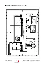
Page 19: ... CAN 19 60 2 4 Z Axis Diagram For machines where mains voltage drops do not occur often ROGLQJ EUDNH 6 6 5 9 9 9 1 86 6 75 6 1 6HW DOZD V 3Q WHUQDO UHVLVWRU K2 K3 3URWHFWLYH DUWK 5 UDNH FRQWURO UHOD DQG RXWSXW WHUPLQDOV DOORFDWHG ZLWK 3Q 3Q 3Q 3Q 3Q 3Q 3Q 3Q 6HW DOVR ...

Page 20: ...Installation manual For machines where mains voltage drops occur often ROGLQJ EUDNH 6 6 5 9 9 9 1 86 6 75 6 1 6HW DOZD V 3Q KA6 K2 KA6 K3 WHUQDO UHVLVWRU 3URWHFWLYH DUWK 5 UDNH FRQWURO UHOD DQG RXWSXW WHUPLQDOV DOORFDWHG ZLWK 3Q 3Q 3Q 3Q 3Q 3Q 3Q 3Q 6HW DOVR ...

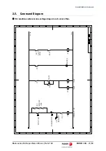
Page 21: ...SD CAN 21 60 2 5 Command Diagram For machines where mains voltage drops do not occur often 9GF 9GF POWER ON K3 BK RY KA2 Z AXIS BREAK K2 KM1 EMERGENCY LINE POWER SPENA K1 PLC 01 K1 K2 POWER KM1 LIMIT BY PASS PLCI1 EMERGENCY X Z Y AXIS HARDWARE LIMITS EMERGENCY STOP ...

Page 22: ... Installation manual For machines where mains voltage drops occur often 9GF 9GF 9DF 9DF KA6 POWER ON K3 BK RY KA2 Z AXIS BREAK K2 KM1 EMERGENCY LINE POWER SPENA K1 PLC 01 K1 K2 POWER KM1 LIMIT BY PASS PLCI1 EMERGENCY X Z Y AXIS HARDWARE LIMITS EMERGENCY STOP ...

Page 23: ...Installation manual Beta series CANopen Servo Drives Ref 2102 BCSD CAN 23 60 2 6 PLC I Os Diagram 3 13876 5HI LV 5HI LV 5HI LV PHUJHQF 3 2873876 LV EUHDN PHUJHQF KA1 KA2 D2 D3 ...

Page 24: ...vo Drives Ref 2102 Installation manual 3 SYSTEM ELECTRICAL DIAGRAM 400 VAC 3 1 Power Diagram 9 1 FRQWURO 9GF 6 V SRZHU 9DF 6 FRQWURO 9DF 6 9DF 32 5 0 16 4 0 SRZHU 9DF 6 0 LV SRZHU 9DF 6 0 LV SRZHU 9DF 6 0 LV 9GF LJLWDO 2 FRQWDFWRU FRLO 9DF ...

Page 25: ...anual Beta series CANopen Servo Drives Ref 2102 BCSD CAN 25 60 3 2 SCD C0 Spindle Compact Drive Diagram 6 63 1 5 9 1 86 6 DRIVE ENABLE 3URWHFWLYH DUWK 3URWHFWLYH DUWK L Re X4 X1 X6 Rext X2 KA3 K2 1 1 6 1 SPEED ENABLE ...

Page 26: ...26 60 BCSD CAN Beta series CANopen Servo Drives Ref 2102 Installation manual 3 3 X Axis Diagram 9 6 6 5 9 WHUQDO UHVLVWRU 1 86 6 6 1 9 6HW DOZD V 3Q K2 3URWHFWLYH DUWK ...

Page 27: ...Installation manual Beta series CANopen Servo Drives Ref 2102 BCSD CAN 27 60 3 4 Y Axis Diagram 6 6 5 9 1 86 6 1 WHUQDO UHVLVWRU 9 9 6 1 6HW DOZD V 3Q 3URWHFWLYH DUWK K2 ...

Page 28: ... Drives Ref 2102 Installation manual 3 5 Z Axis Diagram ROGLQJ EUDNH 5 UDNH FRQWURO UHOD DQG RXWSXW WHUPLQDOV DOORFDWHG ZLWK 3Q 6 6 5 9 3Q 3Q 3Q 3Q 9 9 1 86 6 75 6 1 6HW DOZD V 3Q WHUQDO UHVLVWRU K2 3URWHFWLYH DUWK K3 BK RY 3Q 3Q 3Q 6HW DOVR ...

Page 29: ... 2102 BCSD CAN 29 60 3 6 Command Diagram 9GF 9GF 9DF 9DF KA6 POWER ON K3 BK RY KA2 Z AXIS BREAK K2 KM1 KA3 EMERGENCY LINE POWER SPENA DRENA 1 10 s OFF DELAY K1 PLC 01 K1 K2 POWER KA3 LIMIT BY PASS PLCI1 EMERGENCY X Z Y AXIS HARDWARE LIMITS EMERGENCY STOP KA6 ...

Page 30: ...30 60 BCSD CAN Beta series CANopen Servo Drives Ref 2102 Installation manual 3 7 PLC I Os Diagram 3 13876 5HI LV 5HI LV 5HI LV PHUJHQF 3 2873876 LV EUHDN PHUJHQF KA1 KA2 D2 D3 ...

Page 31: ...E REFERENCE DESCRIPTION LENGTH BSC CS 01 CAN cable between CNC and SCD drive 05 10 15 m BSC CA 02 CAN cable between CNC and BCSD drive 05 10 15 m BSC SA CAN cable between SCD drive and BCSD drive 300 mm BSC AA CAN cable between BCSD drive and BCSD drive 300 mm BSC TR CAN bus terminal resistor BSC PC USB Communication cable between BCSD drive and PC 2 m ACCESSORY BAG FOR LATHES BSC PACK 2AXES 03 AC...

Page 32: ...COMBICON connector Pitch 3 5 mm Characteristics Type Shielded Twisted pairs 1 x 2 x 0 22 mm Flexibility Superflexible Minimum static bending radius of 50 mm and a dynamic radius of 95 mm Cover PUR Impedance Cat 5 100 120 SIGNAL DESCRIPTION ISO GND Ground 0 V CAN L Bus signal LOW SHIELD CAN shield CAN H Bus signal HIGH SHIELD CAN shield I S O G N D C A N L S H I E L D C A N H S H I E L D 1 2 3 4 5 ...

Page 33: ... CNC Pitch 3 5 mm 1x RJ 45 connector on the BCSD Characteristics Type Shielded Twisted pairs 1 x 2 x 0 22 mm Flexibility Superflexible Minimum static bending radius of 50 mm and a dynamic radius of 95 mm Cover PUR Impedance Cat 5 100 120 SIGNAL DESCRIPTION CAN L Bus signal LOW SHIELD CAN shield CAN H Bus signal HIGH 1 2 3 4 5 1 2 3 4 5 P i n P i n 6 7 8 C A N L C A N H C N C C A N A X E S B C S D ...

Page 34: ...male Phoenix MINI COMBICON connector on the SCD C0 Pitch 3 5 mm 1x RJ 45 connector on the BCSD Characteristics Type Shielded Twisted pairs 1 x 2 x 0 22 mm Flexibility Superflexible Minimum static bending radius of 50 mm and a dynamic radius of 95 mm Cover PUR Impedance Cat 5 100 120 SIGNAL DESCRIPTION CAN L Bus signal LOW SHIELD CAN shield CAN H Bus signal HIGH 1 2 3 4 5 1 2 3 4 5 P i n P i n 6 7 ...

Page 35: ... pairs 1x2x0 22 mm One twisted pair is for 485 485 and another one for CAN H CAN L Flexibility Superflexible Minimum static bending radius of 50 mm and a dynamic radius of 95 mm Cover PUR Impedance Cat 5 100 120 PIN SIGNAL DESCRIPTION 1 2 3 485 Signal 485 4 SHIELD CAN shield 5 6 485 Signal 485 7 CAN H Bus signal HIGH 8 CAN L Bus signal LOW S H I E L D 4 8 5 S H I E L D 1 2 3 4 5 1 2 3 4 5 P i n P ...

Page 36: ...s Ref 2102 Installation manual 4 5 Terminal Resistor Cable name BSC TR BCSD axis drive CN4 connector with terminal resistor for the CAN communication end Connector RJ 45 connector 1 2 3 4 5 P i n B C S D C N 4 6 7 8 C A N H C A N L 1 2 0 9 1 1 4 W ...

Page 37: ...or Connecting with RS 485 to all BCSD Axis Drives Cable name BSC PC USB ESView debugging cable Cable to connect from PC A male connector to BCSD axis drive CN4 connector Length 2 m Take out the terminal resistor and use this cable to connect the computer USB line to any of the BCSD drives ...

Page 38: ...18 15 EEC FBS A 15 FBS 08 10 MPC FBS 18 20 EEC FBS A 20 FBS 08 10 MPC FBM 14 3 01 EEC FBM A 03 01 FBM 10 15 20 MPC FBM 14 5 01 EEC FBM A 05 01 FBM 10 15 20 MPC FBM 14 8 01 EEC FBM A 08 01 FBM 10 15 20 MPC FBM 14 10 01 EEC FBM A 10 01 FBM 10 15 20 MPC FBM 14 15 01 EEC FBM A 15 01 FBM 10 15 20 MPC FBM 14 20 01 EEC FBM A 20 01 FBM 10 15 20 MPC FBM 12 3 EEC FBM A 03 FBM 30 50 MPC FBM 12 5 EEC FBM A 05...

Page 39: ...DEF O_BRAKE_Z O20 O_BRAKE Z AXIS REGISTERS CNC STATUS R1 R9 R1 ACTUAL OPERATION MODE OPMODE R2 MAIN CHANNEL OPERATION MODE OPMODA R3 X AXIS DRIVER STATUS R4 Y AXIS DRIVER STATUS R5 Z AXIS DRIVER STATUS R6 SPINDLE DRIVER STATUS CNC CONTROL SIGNALS R15 R19 R15 AUXEND B0R15 AUXEND for STROBE R16 FEEDHOLD B0R16 FEEDHOLD machine with no power B1R16 FEEDHOLD drive X with no torque B2R16 FEEDHOLD drive Y...

Page 40: ... Percentage Spindle Torque R702 P30 SRR702 1 00084 TV2 Percentage X axis Torque R703 P31 SRR703 2 00084 TV2 Percentage Y axis Torque R704 P32 SRR704 3 00084 TV2 Percentage Z axis Torque R705 P33 SRR705 4 00040 SV2 Spindle motor speed R706 P34 SRR706 1 00040 SV2 X axis motor speed R707 P35 SRR706 2 00040 SV2 Y axis motor speed R708 P36 SRR708 3 00040 SV2 Z axis motor speed MARKS M FUNCTIONS M1 M100...

Page 41: ... X drive error DEF M_DRV_X_NPOWER M231 X drive no power DEF M_DRV_X_TORQUE M232 X drive with torque DEF M_DRV_Y_NERR M233 Y drive error DEF M_DRV_Y_NPOWER M234 Y drive no power DEF M_DRV_Y_TORQUE M235 Y drive with torque DEF M_DRV_Z_NERR M236 Z drive error DEF M_DRV_Z_NPOWER M237 Z drive no power DEF M_DRV_Z_TORQUE M238 Z drive with torque DEF M_DRV_S_NERR M239 SX drive error DEF M_DRV_S_NPOWER M2...

Page 42: ...s ERA R1 499 Delete PLC registers SET M_CY1 First PLC scan GEAR1 No spindle gear change END PLC PROGRAM PRG REA CNC STATUS Knowledge of the status of the CNC Manual Automatic in ISO mode Manual Automatic in conversational mode CNCRD OPMODE R1 M_CNCRD ACTUAL OPERATION MODE OPMODE CNCRD OPMODA R2 M_CNCRD MAIN CHANNEL OPERATION MODE OPMODA CUSTOM CNC conversational mode AND NOT B0R2 CNC in execution ...

Page 43: ... with no torque CPS R3 EQ 3 X drive with torque M_DRV_X_TORQUE X drive with torque DRSTAFY B1R4 Y AXIS DRIVE STATUS DRSTASY B0R4 Y AXIS DRIVE STATUS CPS R4 GE 1 Y drive ready M_DRV_Y_NERR Y drive no error CPS R4 LT 2 Y with torque M_DRV_Y_NPOWER Y drive no power CPS R4 LT 3 Y drive without torque B2R16 FEEDHOLD drive Y with no torque CPS R4 EQ 3 Y drive with torque M_DRV_Y_TORQUE Y drive with torq...

Page 44: ...Y_NERR Y drive error AND M_DRV_Z_NERR Z drive error AND M_DRV_S_NERR S drive error O_EMERGEN O_EMERGENCY O_EMERGEN O_EMERGENCY AND NOT M_DRV_X_NPOWER X drive no power AND NOT M_DRV_Y_NPOWER Y drive no power AND NOT M_DRV_Z_NPOWER Z drive no power M_POWER_ON Machine with power NOT M_POWER_ON Machine with power B0R16 FEEDHOLD machine with no power B1R18 START machine with no power B0R19 STOP machine...

Page 45: ...xis drive power ON DRENAZ Z axis drive power ON VERTICAL AXIS BRAKE M_POWER_ON Machine with power AND M_DRV_Z_TORQUE Z drive with torque O_BRAKE_Z O_BRAKE Z AXIS SPINDLE TURN Management of spindle enable M3 M4 M5 M19 SPINDLE STOP DFU M5 Stop spindle RES M_SP1_REQUEST_M3M4 Spindle turn requested RES M_SP1_REQUEST_M19 Spindle orientation requested RESETOUT CNC Reset RESETIN CNC RESET RES M_SP1_REQUE...

Page 46: ...M_SP1_SPENA Spindle turn enable OR M_SP1_REQUEST_M19 Spindle orientation requested OR PLCCNTL PLC control on the PLC SPENAS Spindle drive command ON TG3 3 5000 Spindle disable timer DRENA T3 Spindle disable timer DRENA DRENAS Spindle drive power ON SPINDLE FEEDHOLD M_SP1_REQUEST_M3M4 Spindle turn requested AND NOT REVOK CNC spindle rpm OK AND NOT SERVOSON Close spindle loop AND NOT M_SP1_REQUEST_M...

Page 47: ...APID BUTTON IN MANUAL M_MANUAL CNC manual in any mode AND M_POWER_ON Machine with power AND M_REFERENCE Axis homing done AND B23R562 Rapid button MANRAPID CNC in Manual and RAPID RAPID BUTTON IN AUTOMATIC B0R2 CNC in execution AND M_POWER_ON Machine with power AND M_REFERENCE Axis homing done AND B23R562 Rapid button EXRAPID CNC in Auto and RAPID CNC CONTROL SIGNALS Management of CNC signals AUXEN...

Page 48: ...wer MSG2 Input power M_POWER_ON Machine with power AND NOT M_REFERENCE Axis homing done MSG3 Axis homing PLC ERRORS Management of PLC errors Please write the PLC errors here SERVICE SCREEN Management of the Service screen Service screen will be anabled while pushing the B18R562 and CNC is in ISO FOLLOWING ERROR EXECUTION FOLLOWING ERROR or CONVERSATIONAL screens DFU B18R562 CNC extenal button for ...

Page 49: ...PR 2 0 CNC on minutes SPINDLE RUNNING DFU M2017 1 second marker OR DFD M2017 1 second marker AND DRENAS Spindle drive power ON CUP 4 Spindle ON seconds CPS C4 GE 60 Spindle ON seconds CUP 5 Spindle ON minutes CPR 4 0 Spindle ON seconds CPS C5 GE 60 Spindle ON minutes CUP 6 Spindle ON hours CPR 5 0 Spindle ON minutes OEM PLC Part of the PLC to be developed by the OEM PLEASE WRITE HERE THE PLC PART ...

Page 50: ...BCD EQ 0 M100 M00 CPS MBCD EQ 1 M1 M01 CPS MBCD EQ 2 ERA M1 100 M02 CPS MBCD EQ 3 M3 Spindle CW CPS MBCD EQ 4 M4 Spindle CCW CPS MBCD EQ 5 M5 Stop spindle CPS MBCD EQ 6 M6 Tool change CPS MBCD EQ 8 M8 Coolant ON CPS MBCD EQ 9 M9 Coolant OFF CPS MBCD EQ 19 M19 Spindle orientation CPS MBCD EQ 30 ERA M1 100 End program CPS MBCD EQ 41 M41 Spindle gear 1 CPS MBCD EQ 42 M42 Spindle gear 2 CPS MBCD EQ 43...

Page 51: ...illoscope of the CNC The oscilloscope of the CNC gives access to the following variables of the BCSD drive 6 2 Access to the Variables from the CNC The variables will be identified at the CNC with the SERCOS number Read only variables Write variables All the parameters of the drive may be read and written using the SVAR variable Example P100 SVARn SERCOS ID where n indicates the axis The SERCOS id...

Page 52: ...d for axes and spindles All axes of the channel CNC or PLC must have the same value for a m p ACFGAIN P46 In the BCSD drive system digital CAN a m p ACFGAIN P46 must be set to ADVANCED When setting ACFGAIN ADVANCED in an analog system it will be treated as AFGAIN YES 6 4 Default Parameters of BCSD Axis Drives When initiating the system using WinBCSD a number of default parameters are loaded automa...

Page 53: ...plication demands high current peaks and the mains supply line has too much impedance Check that the power bus plates are tight and the fuse of the power supply I t protection of the crowbar resistor Contact Fagor Automation S Coop Contact Fagor Automation S Coop It has been detected that the parameter checksum is not correct Probably the software version has been changed and the new version requi...

Page 54: ...pulse frequency is too high Something wrong with the inside chip of the 1st channel Something wrong with the inside chip of the 2nd channel At least one of incremental encoder PA PB PC is break off One phase is not connected in the main power supply A power off for more than one period is occurred in AC ERROR 601 Communication error with the rotor encoder ERROR 805 No encoder has been detected on ...

Page 55: ...r or the encoder decoding circuit is faulty Encoder signal is disturbed or the encoder decoding circuit is faulty Encoder signal is disturbed or the encoder decoding circuit is faulty Encoder signal is disturbed or the encoder decoding circuit is faulty The EEPROM data of serial encoder is empty ERROR 9042 Servomotor type error ERROR 9043 Servodrive type error ERROR 9044 Reserved ERROR 9045 Absolu...

Page 56: ...ommunication connection or disturbance The master station sends pulse time timeout The filling time and the cycle of the synchronous signal do not match ERROR 9059 Serial encoder EEPROM data format error ERROR 9060 Communication module not detected ERROR 9061 Communication module or CPU error ERROR 9062 Servodrive cannot receive periodic data from communication module ERROR 9063 Communication modu...

Page 57: ...Beta series CANopen Servo Drives Ref 2102 BCSD CAN 57 60 User notes Installation manual ...

Page 58: ...58 60 BCSD CAN Beta series CANopen Servo Drives Ref 2102 User notes Installation manual ...

Page 59: ...Beta series CANopen Servo Drives Ref 2102 BCSD CAN 59 60 User notes Installation manual ...

Page 60: ...series CANopen Servo Drives Ref 2102 Fagor Automation S Coop B º San Andrés 19 Apdo 144 E 20500 Arrasate Mondragón Gipuzkoa Spain Tel 34 943 039 800 Fax 34 943 791 712 E mail info fagorautomation es www fagorautomation com ...

Reviews: