background image

pag 22

!

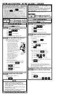
IMPORTANT: programming Junior is performed at first installation. Even in absence of mains power    , programming is

stored  for  any  changes  in  the  position  of  slow  programming  can  be  performed  by  the  same  procedure.

Adjust the Trimmer Force necessary to move the gate. This adjustment also determines the strenght and impact resistance

with an obstacle  in slowdown.  An high force to inertia of the gate is leads to incorrect installation according to safety

regulation EN 12445 and EN 12453

=

=

PROGRAMMING AND SELF LEARNING OF THE OPERATION RUN

1° Operation:

 unlock by opening until it stops ( beyond 90°), the unlocking handle with the coded key, freeing the gate from the Junior

ioperator, then position the gate at about half of its run. Recover the lock closing the handle as a safety measure, when the unlocking

handle is freed, the electrical power supply to the  Elpro 62 PCB is disconnected

2° Operation:

 Remove the electrical power supply to the electronic PCB by completely extracting the 230 v line fuse from its seat,

found on the front, underneath the Elpro 62 PCB.

Push and hold down  the 

P botton

  and then afterwards install the line fuse. After 2-3 seconds release the P button: the LP LED will begin

to flash signalling theprogramming phase

+90°

LP

LP

3° Operation: learning of the run pattern and sowdowns.

It is possible to performe programming with the dedicated P button or else with an impulse from  the coded transmitter.

It is important that both and stops, those for opening and closing, are installed. Position the magnetic or mechanical limit switches in

correspondence  with  the  final  opening  and  closing  positions  for  the  magnetic  detector  or  for  the  Junior  feeler.

Push with an impulse: the Junior

will  begin  to  move  the  gate  in

opening

LP

Beginning  of  the  slowdown

Push with an impulse: the  junior

will begin to slowdown until the

limit switch is detected

Push with an impulse: the Junior

move the in closing

Beginning  of  the  slowdown

Push with an impulse : the Junior

will begin to slow down until the

limit switch is detected

3.1

3.2

3.3

3.4

3.2

3.3

3.4

FA

D

IN

I

normal  speed

slowdown

slowdown

Fig. 18

Fig. 19

 Fig. 20

Fig. 21

Fig. 22

Fig. 23

Fig. 24

Programming  end: 

adjust  the

Trimmer Force necessary to move

the gate

LP

LP

LP

LP

2-3 sec

LP

3.1

LP

Fig. 25

Fig. 26

Fig. 27

Fig. 28

Fig. 29

-

+

-

+

Junior 624  - 24V dc

meccanica

FADINI

Elpro  62

GB

Summary of Contents for Elpro 62

Page 1: ...LULE SONO ALIMENTATI ATTRAVERSO I MORSETTI DEDICATI 13 14 Fig 17 DEL LIBRETTO ISTRUZIONI PENA IL BLOCCO COSTANTE DEL CANCELLO GB IMPORTANTE IMPORTANT Junior 624 Junior 633 Junior 650 THE CONTROL BOARD...

Page 2: ...45 I Libretto di istruzioni pag 1 16 GB Instructions Manual pag 1 8 17 24 F Notice de montage pag 1 8 25 32 D Betriebsanleitung pag 1 8 33 40 E Manual de instrucciones pag 1 8 41 48 NL Instructieboekj...

Page 3: ...pi ces entretoises et boulons de fixation pas compris dans le kit E Componentes principales para una instalaci n del Junior 624 en la Fig 1 1 Motorreductor deslizante electromec nico serie Junior con...

Page 4: ...de course magn tique P Pignon m4 Z18 Q Couvercle du programmateur R Transformateur 230V 24V 150VA pour Junior 624 E Lista de los componentes principales ilustrados en la Fig 2 A Luz de led azul y mbar...

Page 5: ...03A 6 Lampe clignotante Miri 4 avec antenne 7 Emetteur radio 8 S lecteur cl CHIS 37 Attention v rifier l int grit de la structure et la lin arit du mouvement du portail en liminant d ventuels frotteme...

Page 6: ...pag 5 Fig 5 Fig 6 60mm 60mm Fig 7 Fig 8 60mm 60mm...

Page 7: ...pag 6 Fig 9 96mm 96mm 60mm 96mm 60mm 2mm Fig 10 96mm 60mm 96mm 60mm 2mm 22x8 6 5 M8 96mm...

Page 8: ...pag 7 Fig 11 Fig 12 1 2 3 1 2 3 Fig 13...

Page 9: ...INKS IZQUIERDA LINKS I Finecorsa magnetico GB Magnetic limit switch F Fin de course magn tique D Magnetischer Endschalter E Final de carrera magn tico NL Magnetische eindslag I Finecorsa meccanico GB...

Page 10: ...ction wires 5A 22V 230V F2 6 3A Battery Radiocont act LED Card Elpro 62 for JUNIOR 624 24V dc Fuse terminal Output for 2 sliding leaf Elpro 62 SLAVE terminal for 2 sliding operator Dip Switch 12 ON CL...

Page 11: ...closing slow down reverse run upon contact with an obstacle and LED diagnostics Set up for double sliding exit defined by the way of Dipswitches of the RH nad LH installation Blue Amber LED lamp on th...

Page 12: ...nels All thepossible configurations are attached to their respective command accessories FADINI Output 24V FADINI FADINI Astro 43 FADINI NC NC 1 2 3 4 5 6 NC OPEN CLOSE STOP COMMON RADIO CONTACT COMMO...

Page 13: ...ro 62 MASTER Elpro 62 SLAVE Dip Switch 12 OFF Dip Switch 12 ON terminal 15 open terminal 4 open terminal 16 close terminal 5 close terminal 17 23 common terminal 3 common terminal 22 terminal 16 close...

Page 14: ...OPEN NA External clock Opening by way of external clock Connection connect the NA contact of the clock with terminal 4 OPEN and terminal 3 COMMON in parallel enabling the automatic closing with the D...

Page 15: ...Push and hold down the P botton and then afterwards install the line fuse After 2 3 seconds release the P button the LP LED will begin to flash signalling theprogramming phase 90 LP LP 3 Operation lea...

Page 16: ...onnected to the mains at the PCB IMPORTANT Once the electrical power suply has been disconnected using the unlocking key upon return of the mains electrical power the first movement of the Junior oper...

Page 17: ...mprovement TECHNICAL SPECIFICATIONS AND DIMENSIONS 316 293 140 102 62 5 40 170 38 210 95 40 170 210 296 55 290 160 Technical specifications Electrical power supply 230V 50Hz Motor voltage 24Vdc Max El...

Page 18: ......

Page 19: ......

Page 20: ...ch ohne Vorank ndigung vorzunehmen und bernimmt f r etwaige Fehler bzw Sach und Personensch den keinerlei Haftung El fabricante se reserva el derecho a aportar modificaciones al presente manual sin pr...

Reviews: