


SPRINT 382 - SPRINT 383
7
00058I0112 - Rev.6
Tr
ansla
tion of the original instruc
tions
ENGLISH
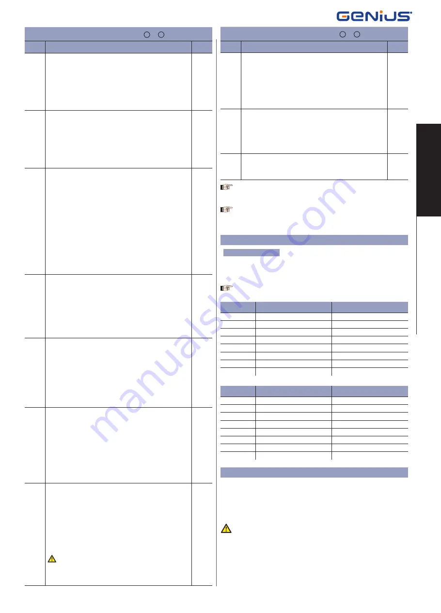
ADVANCED PROGRAMMING F + +
Display
Function
Default
Ph
CLOSING PHOTOCELLS LOGIC:
Select the tripping mode of the closing photocells.
They operate for the closing movement only: they stop move-
ment and reverse it when they are released, or they reverse it
immediately.
Y
= Reverse on release
no
= Reverse immediately when opening
no
oP
OPENING PHOTOCELLS LOGIC:
Select the tripping mode of the opening photocells.
They operate for the opening movement only: they stop the
movement and restart it when they are released, or they reverse
it immediately.
Y
= Reverse immediately when closing
no
= Restart movement on release
no
EC
ENCODER:
If the encoder is used, you may select its presence.
If the encoder is present and enabled, “decelerations” and “partial
opening” are controlled by the encoder (see relevant paragraphs).
The encoder operates as an anti-crushing device: If the gate
strikes an obstacle during opening or closing, the encoder
immediately reverses gate leaf movement for 2 seconds. If the
encoder operates again during the 2-seconds reversing time, it
stops movement (STOP) without commanding any reversing. If
no sensor is supplied, the parameter must be set on
00
. If there
is the encoder, adjust the sensitivity of the anti-crushing system,
by varying the parameter between
01
(maximum sensitivity) and
99
(minimum sensitivity).
From
01
to
99
= Encoder active and sensitivity adjustment
00
= Encoder disabled
00
rP
Pre-limit switch DECELERATION:
You can select gate deceleration before the opening and closing
limit-switches have been tripped.
Time can be adjusted from
00
to
99
.
If an encoder is used, the adjustment is not determined by time
but by motor revs, thus obtaining greater deceleration precision.
00
= Deceleration disabled
from
01
to
99
= Deceleration enabled
10
rA
Post-limit switch DECELERATIONS:
You can select gate deceleration after the opening and closing
limit-switches have been tripped.
Time can be adjusted from
00
to
20
sec. in 0.04-second steps.
If an encoder (optional) is used, the adjustment is not determined
by time but by motor revs, thus obtaining greater deceleration
precision.
00
= Deceleration disabled
from
01
to
20
= Deceleration enabled
05
PO
PARTIAL OPENING:
You can adjust the width of leaf partial opening.
Time can be adjusted from
01
to
20
sec. in 0.1-second steps.
If an encoder (optional) is used, the adjustment is not determined
by time but by motor revs, thus obtaining greater precision of
partial opening.
E.g.
for a gate with a sliding speed of 10 m /min, value
10
corre-
sponds to about 1.7 metres of opening.
E.g.
for a gate with a sliding speed of 12 m /min, value
10
corre-
sponds to about 2 metres of opening.
05
t
WORK TIME:
We advise you to set a value of 5 to 10 seconds over the time
taken by the gate to travel from the closing limit-switch to the
opening limit-switch and vice versa. This will protect the motor
against any overheating if a limit-switch fails.
Adjustable from
0
to
59
sec. sec. in one-second steps.
Subsequently, viewing changes to minutes and tens of seconds
(separated by a point) and time is adjusted in 10 second steps,
up to a maximum value of
4.1
minutes.
E.g.
if the display shows
2.5
, work time is 2 min. and 50 sec.
The set value does not exactly match the motor’s ma-
ximum operating time, because the latter is modi
fi
ed
according to the performed deceleration spaces.
2.0
ADVANCED PROGRAMMING F + +
Display
Function
Default
AS
ASSISTANCE REQUEST (combined with next function):
If activated, at the end of countdown (settable with the next fun-
ction i.e. “Cycle programming”) it effects 2 sec. of pre-
fl
ashing (in
addition to the value already set with the PF function) at every
Open pulse (job request). Can be useful for setting scheduled
maintenance jobs.
Y
= Active
no
= Disabled
no
nc
CYCLE PROGRAMMING:
For setting countdown of system operation cycles. Settable (in
thousands) from
00
to
99
thousand cycles.
The displayed value is updated as cycles proceed.
This function can be used to check use of the board or to exploit
the “Assistance request”.
00
St
GATE STATUS:
Exit from programming and return to gate status viewing (see
Chpt 5.1.).
To reset the programming default settings, check if the edge input is
opened (SAFE LED OFF), and simultaneously press keys
+
,
-
and
F
, holding
them down for 5 seconds.
Modification of programming parameters comes into effect immediately,
whereas definitive memory storage occurs only when you exit program-
ming and return to gate status viewing. If the equipment is powered down
before return to status viewing, all modifications will be lost.
6. START-UP
6.1. INPUTS CHECK
The table below shows the status of the LEDs in relation to to the status of the inputs.
Note the following:
Led lighted
= closed contact
Led off
= open contact
Check the status of the LEDs as per Table.
The status of the LEDs while the gate is closed at rest are shown in bold.
dl = -3
= Right-hand opening movement
LEDS
LIGHTED
OFF
FCA
Limit-switch free
Limit-switch engaged
FCC
Limit-switch free
Limit-switch engaged
OPEN B
Command activated
Command inactive
OPEN A
Command activated
Command inactive
FSW OP
Safety devices disengaged
Safety devices engaged
FSW CL
Safety devices disengaged
Safety devices engaged
STOP
Command inactive
Command activated
EDGE
Safety devices disengaged
Safety devices engaged
dl = 3-
= Left-hand opening movement
LEDS
LIGHTED
OFF
FCA
Limit-switch free
Limit-switch engaged
FCC
Limit-switch free
Limit-switch engaged
OPEN B
Command activated
Command inactive
OPEN A
Command activated
Command inactive
FSW OP
Safety devices disengaged
Safety devices engaged
FSW CL
Safety devices disengaged
Safety devices engaged
STOP
Command inactive
Command activated
EDGE
Safety devices disengaged
Safety devices engaged
7. AUTOMATED SYSTEM TEST
When you have
fi
nished programming, check if the system is operating correctly.
Most important of all, check if the force is adequately adjusted and if the safety devi-
ces are operating correctly. Veri
fi
care soprattutto l’adeguata regolazione della forza
e il corretto intervento dei dispositivi di sicurezza. Make sure it has been adjusted
correctly by using an impact force tester in accordance with standard EN 12453. For
non-EU countries, if there are no speci
fi
c local regulations, the static force must be
less than 150 N.
If the impact force limits indicated in the standard have been met using the
pre-limit switch deceleration, the function
Sr
=
Y
in advanced programming
has to be enabled: every time power is turned on / restored, the leaf moves at
a slow speed until it has travelled completely between one limit switch and
the other.
DECELERATION
- The deceleration is carried out only after a complete cycle has
taken place from one limit switch to the other. Each time the power is turned on/
restored, the cycles carried out before the complete movement take place at normal
or slow speed according to parameter
Sr
in advanced programming.
Summary of Contents for GENIUS Sprint 382
Page 13: ...746 E R 41 732099 Rev D...
Page 14: ......