14
FC2
FC1
Fig. 21
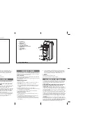
Fig. 22
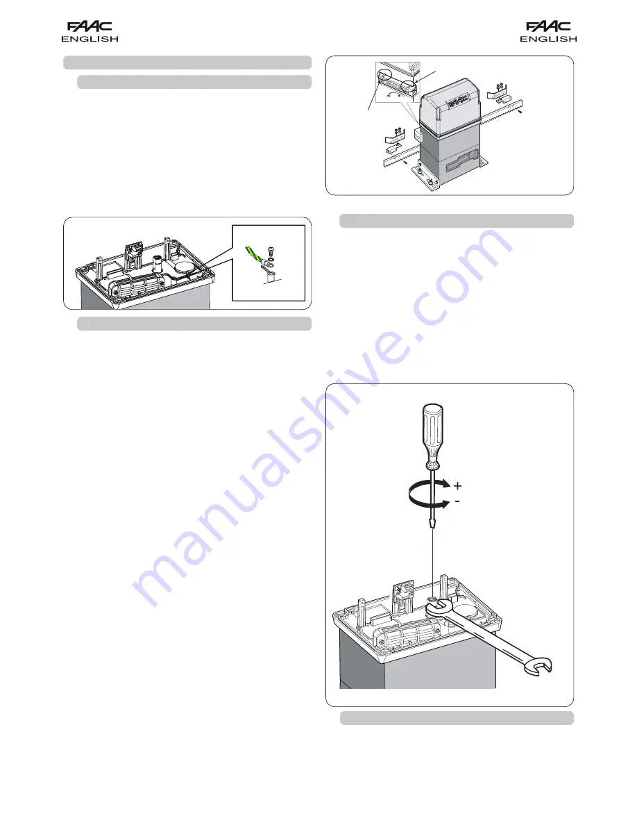
Fig. 23
6.
START-UP
6.1.
ELECTRIC CONNECTIONS
!
!
!
!
!
Before attempting any work on the control unit (connections,
programming, maintenance), always turn off power supply.
Observe points 10, 11, 12, 13 and 14 of the GENERAL SAFETY
OBLIGATIONS.
Make all the electric connections on the board as shown in
chapter 5, including earthing the operator (Fig. 21).
6.3.
ADJUSTING THE MECHANICAL CLUTCH
The 844R 3Ph operator is equipped with a mechanical clutch.
Procedure for adjusting the action threshold of the mechanical
clutch (we advise you to set it in compliance with current
standards):
1)
Cut power to the automated system.
2) Keep the motor shaft locked with a wrench, and turn the
clutch adjustment screw with an Allen wrench or screwdriver
Fig. 23.
To increase torque, turn the screw clockwise.
!
The operator is supplied with clutch set to maximum value.
Therefore, you should initially turn the screw counter-
clockwise to reach optimum setting.
To reduce torque, turn the screw counter-clockwise.
3) Power up the automated system and check if the torque
you have just carried out is correctly set.
The 844R 3Ph operator has an inductive limit sensor (fig. 1 ref.
햴
),
with a quick-fit connector already connected to the 844
INTERFACE board. When the sensor detects a transiting plate
fitted on the top of the rack, it commands gate motion to stop.
Procedure for correct positioning of the two supplied plates:
1)
Assemble the limit sensor centring the plate with respect
to the threaded pins of the support (fig.22).
2)
Check if the operator is in manual mode (see chapter 8).
3)
Manually take the gate to opening position, leaving 2 - 5
cm from the mechanical travel stop.
4)
Allow the plate to slide on the rack in opening direction
until the relevant LED goes OFF.
5)
Take the plate about a further 45 mm and secure it to
the rack, fastening the screws.
6)
Manually take the gate to closing position, leaving 2 - 5
cm from the mechanical travel stop.
7)
Allow the plate to slide on the rack in closing direction
until the relevant LED goes OFF.
8)
Take the plate about a further 45 mm and secure it to
the rack, fastening the screws.
9)
Take the gate to its halfway travel point and relock the
system (see chapter 9).
10)
Run the automated system for at least one complete
cycle.
11)
Check if the gate stops at about 2-5 cm from its
mechanical contact point. If necessar y, correct the
position of the plates and check if the stop point is correct.
12)
The distance between the inductive limit sensor and the
plates must be 5 mm at the most.
6.2.
ADJUSTMENT OF INDUCTIVE LIMIT SENSOR
6.4.
CHECK OF SAFETY DEVICES AND ACCESSORIES
Check correct operation of the following: all safety and anti-
crushing devices and the accessories used in the system.