


Chapter 5
Unpacking and Installing the Switch
5 - 6
This guards against the switch sliding out during an extreme event, such as
an earthquake.
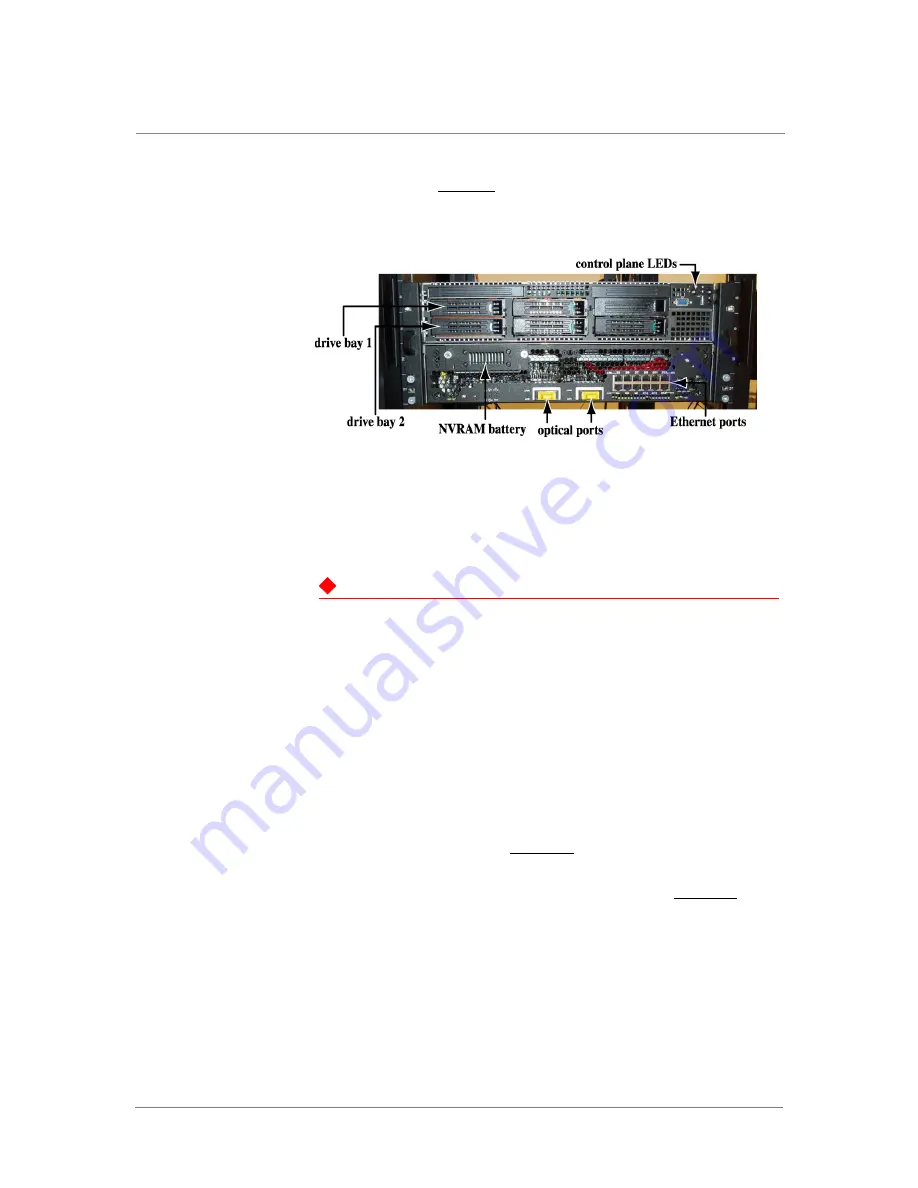
See
, which shows both the control plane and the data
plane installed in a standard rack
Figure 5.1
Front Panel – No Bezel
Attaching the PCI-E Cable and Power Cords
DANGER
Before powering on the switch, make sure all AC outlets to the switch are
properly grounded. Never assume that power is disconnected from a circuit;
always check.
The power button powers up the switch or places the switch in sleep mode.
Sleep mode is accomplished by pressing and holding the power button for 5
seconds. To fully remove power from the system, you must unplug all 4 AC
power cords from wall outlets.
1. Attach the PCI-E cable.
2. Attach power cords to the DP power supplies. Attach one DP power
supply to one AC line feed and the second DP power supply to a
separate line feed. See
for the plug locations; the DP is
on the bottom.
3. Attach power cords to the CP power supplies. See
for the
plug locations; the CP is on the top.
Summary of Contents for ARX-4000
Page 1: ...ARX 4000 Hardware Installation Guide version 4 00 001 810 0055 00 ...
Page 2: ......
Page 5: ...Table of Contents ...
Page 6: ......
Page 9: ......
Page 10: ...Table of Contents x ...
Page 12: ......
Page 22: ......
Page 28: ...Chapter 2 Product Overview 2 8 ...
Page 30: ......
Page 38: ......
Page 50: ......
Page 56: ...Chapter 5 Unpacking and Installing the Switch 5 8 ...
Page 58: ......
Page 70: ...Chapter 6 Connecting the Switch to the Network 6 14 ...
Page 72: ......
Page 76: ...Chapter 7 Operational Status and Troubleshooting 7 6 ...
Page 78: ......
Page 90: ...Appendix A Removing and Replacing FRUs A 14 ...
Page 91: ...Index ...
Page 92: ......