background image


SW HDMI Series • Remote Communication and Control

31

12. 

If you want to remove a device from the Devices section, do the following:

a. 

Click on the names of the devices to be deleted, to highlight them.

b. 

Select 

Remove


Selected


Device(s)

 from the 

Edit

 menu.

c. 

On the Remove Device(s) window, select or deselect any devices on the list as 
desired, then click 

Remove

.

To remove 

all

 devices, select 

Remove


All


Devices

 from the 

Edit

 menu.

13. 

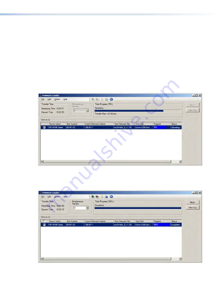
Click 

Begin

. The following indicators show the progress of the update:

• 

The Transfer Time section shows the amounts of remaining and elapsed time for 
the update.

• 

The Total Progress section displays a progress bar with 

Uploading...

 above it.

• 

In the Devices section, the Progress column displays an incrementing percentage 
and another progress bar. The Status column displays 

Uploading

.

Figure 21. 

Firmware Upload in Progress

14. 

The upload is complete when the 

Remaining


Time

 field shows 

00.00.00

, the 

Progress column shows 

100%

, and 

Completed

 is displayed above the progress bar 

and in the 

Status

 field. Close the Firmware Loader window.

Figure 22. 

Firmware Upload Complete

Summary of Contents for SW HDMI Series

Page 1: ...User Guide SW HDMI Series HDMI Switchers Two and Four Input HDMI Switchers 68 2312 01 Rev A 04 13...

Page 2: ...uf aufmerksam machen dass im Inneren des Geh uses dieses Produktes gef hrliche Spannungen herrschen die nicht isoliert sind und die einen elektrischen Schlag verursachen k nnen VORSICHT Dieses Symbol...

Page 3: ...d in this guide are the properties of their respective owners The following Registered Trademarks R Registered Service Marks SM and Trademarks TM are the property of RGB Systems Inc or Extron Electron...

Page 4: ...mmands and examples of computer or device responses mentioned in this guide the character 0 is used for the number zero and O is the capital letter o Computer responses and directory paths that do not...

Page 5: ...nput 15 Resetting 16 Using the Optional IR 102 Remote Control 16 Locking and Unlocking the Front Panel Executive Mode 17 EDID Modes 17 Remote Communication and Control 21 Using Simple Instruction Set...

Page 6: ...SW HDMI Series Contents vi...

Page 7: ...iant with High bandwidth Digital Content Protection HDCP The SW HDMI switchers can be controlled via the front panel the RS 232 interface contact closure or the optional IR 102 Remote Control You can...

Page 8: ...reloads the user assigned EDID information It then writes the information to non volatile memory on the inputs The input devices can read this information as they reboot see EDID Modes on page 17 for...

Page 9: ...00 LINK ACT COM IR INPUT RELAY TX RX R IPL 250 ON OFF DISPLA Y MUTE SCREE N UP SCREE N DOWN VCR DVD DOC CAM LAPTO P PC Laptop DSS Receiver Blu ray Player Extron SW4 HDMI Switcher PC HDMI Cables RS 232...

Page 10: ...S 232 port Pins 1 2 and 3 of the Remote port for serial RS 232 control see Wiring for RS 232 Control on page 8 for connection procedures Config port USB mini B connector for USB control see Connecting...

Page 11: ...es to these Type A female single link HDMI connectors Data rates of up to 6 75 Gbps are supported LockIt brackets LockIt cable lacing brackets one for each HDMI input and the output connector are prov...

Page 12: ...ort also enables you to select an input via a push button contact closure device see Wiring for Input Selection by Contact Closure e Remote and auto input switching connector This 5 pole 3 5 mm captiv...

Page 13: ...ance certification and may cause damage to the supply and the switcher 1 Cut the DC output cord to the length needed 2 Strip the jacket to expose 3 16 inch 5 mm of the conductors ATTENTION Exposing mo...

Page 14: ...plugs into the Tx transmit port Connect the receive wire to pin 2 which plugs into the Rx receive port Connect the ground wire to pin 3 which plugs into the G ground port 2 Plug the 5 pole connector...

Page 15: ...l SW4 HDMI HDMI SWITCHER 1 IR CONFIG SIGNAL INPUTS INPUTS OUTPUT 1 2 3 4 HDCP 2 3 4 AUTO SWITCH Figure 6 USB Port Connection 2 If this is the first time you have connected an SW HDMI to this USB port...

Page 16: ...he Install the software automatically Recommended radio button then click Next you do not need to insert a disc Figure 8 Selecting the Radio Button to Install the USB Driver Automatically Your compute...

Page 17: ...the wire into slots 4 and 5 of the provided 5 pole captive screw plug connecting pins 4 and 5 together 3 Use a small screwdriver to tighten the two screws above pin slots 4 and 5 of the plug so that t...

Page 18: ...indicator device such as an LED to the Tally Out port When the input you are using is selected the V pin of the Tally Out port emits a 5 V volt signal which activates the connected indicator To conne...

Page 19: ...MI SWITCHER 1 IR CONFIG SIGNAL INPUTS INPUTS OUTPUT 1 2 3 4 HDCP 2 3 4 AUTO SWITCH 3 2 1 5 4 6 Figure 11 SW4 HDMI Front Panel a Auto Switch LED This LED lights when auto input switching is in effect s...

Page 20: ...d input is HDCP encrypted requires HDCP authentication the corresponding signal LED may not light unless HDCP has been authenticated Output The Output Signal LED lights when a TMDS signal is being tra...

Page 21: ...on the front panel ensure that auto input switching is not enabled The LED corresponding to the selected input button lights The appropriate front panel input LED lights to indicate the selected inpu...

Page 22: ...4 HDMI HDMI SWITCHER 1 IR CONFIG SIGNAL INPUTS INPUTS OUTPUT 1 2 3 4 HDCP 2 3 4 AUTO SWITCH 40 40 30 Maximum Channel IR 102 0 1 2 3 4 5 6 7 8 9 10 Universal Remote Figure 12 Area for Remote Signal Rec...

Page 23: ...ources whether or not any of the sources are selected EDID information consists of the display resolution refresh rate data rate supported audio formats and other parameters By factory default the EDI...

Page 24: ...table on the next page shows the EDID files that are provided with the switcher User loaded EDID file In addition to the 48 EDID files provided with the switcher four empty memory locations 50 throug...

Page 25: ...n a 97 75 MHz 40 1080p 60 Hz HDTV HDMI 2 Ch 148 5 MHz 14 1920 x 1080 60 Hz PC DVI n a 148 5 MHz 41 720p 50 Hz HDTV HDMI Multi Ch 74 25 MHz 15 1920 x 1200 60 Hz PC DVI n a 154 MHz 42 720p 60 Hz HDTV H...

Page 26: ...mat DVI These are 128 byte EDID files which specify a DVI sink They do not contain an extension block HDMI These are 256 byte EDID files each containing a CEA extension block They each specify an HDMI...

Page 27: ...se commands from your computer using a communication software program such as Extron DataViewer or HyperTerminal When the switcher determines that a command is valid it executes the command and sends...

Page 28: ...the command and response table ASCII to Hex Conversion Table Space Figure 14 ASCII to Hex Conversion Table Symbol Definitions CR LF carriage return with line feed hex 0D 0A or Soft carriage return no...

Page 29: ...ion 0 HDCP not authenticated 1 HDCP authenticated X1 Signal status 0 no signal detected 1 signal detected X1 On and off or enabled and disabled status 0 off or disabled 1 on or enabled X1 Switch mode...

Page 30: ...bit Signal Status Request status of all signals E LS Sig X1 X1 X1 or Sig X1 X1 X1 X1 X1 Show signal presence or absence for all inputs and the output For X1 0 no signal detected 1 signal detected Req...

Page 31: ...X 1 locked 0 unlocked default View lockout status X X Show executive mode On or Off status Front Panel IR Receiver Enable and Disable Enable and disable IR receiver X1 65 IRDisable X1 Disable the IR r...

Page 32: ...ription Information Requests continued Query firmware version Q X Show firmware build number X expressed to the second decimal place Example Q 1 01 Query auto input switching status 72 Asw X1 Show sta...

Page 33: ...e 15 Firmware Loader Download Link 4 On the next screen enter the requested information then click the Download fw_loader_vnxn exe button where nxn is the Firmware Loader version number 5 Follow the i...

Page 34: ...ins of the switcher Remote port see Wiring for RS 232 Control on page 8 or the front panel USB port see Connecting to the USB Port on page 9 2 If you have not already done so download and install the...

Page 35: ...Click the Browse button in the New Firmware File Optional section 10 On the Open window navigate to the new firmware file which has an S19 extension and double click it Figure 18 Open Window for Firmw...

Page 36: ...w and the Add Device window closes If you will be uploading the firmware to multiple SW HDMI switchers that are connected to your computer do the following a Click Add Next Your first device is added...

Page 37: ...following indicators show the progress of the update The Transfer Time section shows the amounts of remaining and elapsed time for the update The Total Progress section displays a progress bar with Up...

Page 38: ...ed air flow Install the equipment in a rack so that the amount of air flow required for safe operation of the equipment is not compromised 3 Mechanical loading When mounting the equipment in the rack...

Page 39: ...ting The SW HDMI can also be mounted vertically to the front or rear rack supports using the optional MBB 100 Back of the Rack Mounting Kit as follows 1 If rubber feet were previously attached to the...

Page 40: ...ble or podium use the optional MBU 123 Mini Under Desk Mounting Kit as follows 1 If rubber feet were previously attached to the bottom of the unit remove them 2 Remove the two screws from each side of...

Page 41: ...ide the unit slightly forward or back then tighten all four screws to secure it in place Rack mounting options The following table lists the rack mounting shelves and kits that are available rack from...

Page 42: ...and Africa Extron Europe Hanzeboulevard 10 3825 PH Amersfoort The Netherlands China Extron China 686 Ronghua Road Songjiang District Shanghai 201611 China Asia Extron Electronics Asia Pte Ltd 135 Joo...

Reviews: