


IPCP 505 • Software-based Configuration and Control
36
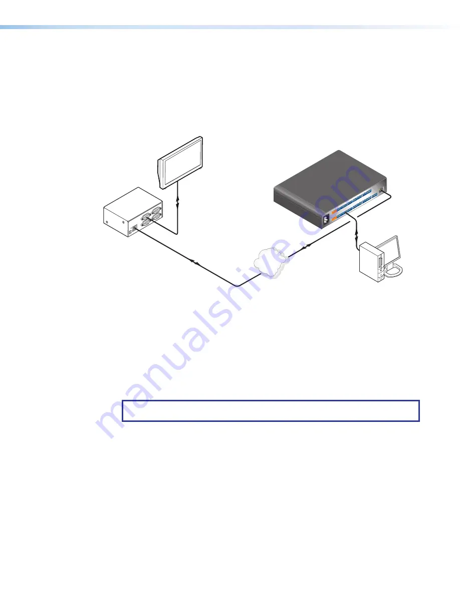
Hardware connection
To set up the hardware for serial bridging:
1.
Verify that the protocol (baud rate, data bits, stop bits, parity) is identical for both serial
ports that will be “bridged” (one port on each IPCP or IPL unit).
2.
For unit 1 (the remote IPCP or IPL device), connect a serial cable to an AV device such
as a display or projector (see figure 23,
1
).
3.
Connect that same remote IPCP or IPL (unit 1) to the LAN (see
2
).
FLE
X I
/O
SW
ITC
HE
D 1
2VDC
40W
MA
X T
OTA
L
LA
N
1
2
3
4
CO
M1
TX
RX
RTS
CT
S
IR/
SE
RIA
L
1
S
G
S
G
2
RE
LA
Y
3
S
G
S
G
+ -
+ -
+ -
+ -
4
1
2
1
2
3
4
3
4
5
S
G
S
G
6
7
S
G
S
G
8
5
6
7
8
CO
M2
TX
RX
CO
M3
TX
RX
CO
M7
TX
RX
CO
M4
TX
RX
RTS
CT
S
CO
M5
TX
RX
CO
M6
TX
RX
CO
M8
TX
RX
5A
MAX
100
-24
0V
50-
60H
z
CO
M 3
LA
N
UID
# 0
93012052
PO
WER
12V
.5A
MAX
CO
M 2
COM
1
COM
2
G
G
G
G
G
G
G
G
G
RS-232
Plasma Display
Extron
IPL T S4
Control Processor
(unit 1)
Ethernet
Extron
IPCP 505
IP Link
®
Control Processor
(unit 2)
Remote User Control and
Administrator Monitoring
Ethernet
RS-232
1
1
1
1
1
1
1
1
2
2
2
2
2
2
2
2
3
3
3
3
3
3
3
3
4
4
4
4
4
4
4
4
TCP/IP
Network
Figure 23.
Connections for Serial Bridging
4.
For unit 2 (the local IPCP or IPL device), make a serial connection to the PC or controller
that is to control the remote AV device (see
3
).
5.
Connect the local IPCP or IPL device (unit 2) to the same network (see
4
).
You are now ready to configure unit 2 (the local IPCP or IPL device) for serial bridging mode.
Serial bridge configuration
To allow both units to communicate together, you must configure unit 2 to communicate
with unit 1.
NOTE:
If a serial (RS-232) driver was previously loaded (via Global Configurator) onto
the IPCP unit, serial bridging disables it.
To configure unit 2:
1.
Enter the IP address of unit 2 in the browser
Address
field at the top of the screen, and
press the <
Enter
> key. The
System Status
page opens, showing the current IP and
serial port settings of unit 2.


