3
Rear Panel Overview
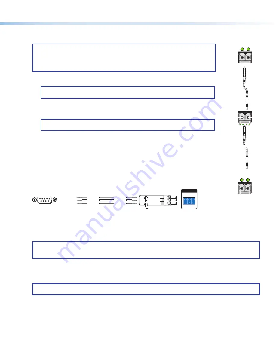
Fiber optic boards with connectors and LEDs
NOTES:
•
Ensure the proper fiber cable for the I/O board is used. Typically, singlemode fiber has a
yellow jacket and multimode cable has an orange or cyan jacket.
•
The FOX3 matrix switcher uses one connector on the block as an input and the second
connector on the same block as a separate output.
1
Input connector
— Connect a fiber optic cable between each Input LC connector and a FOX3
transmitter or any other compatible Extron FOX device.
NOTE:
For USB, return audio, and serial RS-232 (receiver-to-transmitter) function, connect
the far end to the Optical Out connector on a FOX receiver.
Input LED
— See
Fiber optic I/O board LED indication
2
Output connector
— Connect a fiber optic cable between each output LC connector and a
FOX3 receiver or any other compatible Extron FOX device (see
NOTE:
For USB, return audio, and serial RS-232 (receiver-to-transmitter) function, connect
the far end to the Optical In connector on a FOX transmitter.
Output LED
— See
Fiber optic I/O board LED indication
Replaceable fans
— This fan card has 3 removable fans (see
on page 12 to replace a fan).
LAN Ethernet port
— Optionally, connect a network WAN or LAN hub, a control system, or a
computer to the Ethernet RJ-45 port.
•
Network connection
— Wire as a patch (straight) cable.
•
Computer or control system connection
— Wire the interface cable as a crossover cable.
Remote RS-232 port
— Optionally, connect a control system or computer to the rear panel Remote
RS-232 port (see figure 3 for wiring).
RS-232
Tx Rx G
REMOTE
Transmit
Receive
Receive
Transmit
Ground
Ground
DB9 Pin Locations
Female
5
1
9
6
Pin 2 = Rx
Pin 3 = Tx
Pin 5 = G
Computer
Figure 3.
RS-232 Connector Wiring
Reset button and LED
— Initiate four levels of reset of the matrix switcher. For different reset levels, press and hold the
recessed button while the switcher is running or while powering up the switcher (see the
FOX3 80x User Guide
, available at
for more information on the reset modes).
NOTE:
The factory configured passwords for all accounts on this device have been set to the device serial number.
In the event of a complete system reset, the passwords convert to the default, which is
extron
for the
Admin
and no
password for the
User
.
Power supplies
— The Primary and Redundant power supplies are hot-swappable. There are two corresponding LEDs on
the front panel that indicate the status of each power supply (see
Removing and Installing a Power Supply Module
page 12 to replace power supplies).
Power connectors
— Plug the switcher into two grounded AC sources.
NOTE:
For reliability, connect the Redundant power cord to either an uninterruptible power source or to a power source
that is completely independent from the primary power source.
3
OUT
IN
*
Optional for
return data
OUTPUTS
Transmitting
Unit
Receiving
Unit
FOX3 Matrix
Switcher
A
IN*
*
Optional for
return data
1
OUT
INPUTS
A
IN
OUT*
2
2
1
1


