7
Command
ASCII Command
(Host to Unit)
Response
(Unit to Host)
Additional Description
View individual video input
signal status
E
X!
LS
}
Verbose mode 2/3
X1(]
In
X!
•
X1(
]
View all video input signal
status
E
0LS
}
Verbose mode 2/3
X1(
1
X1(
2
...
X1(
n
]
In00
X1(
1
X1(
2
...
X1(
n
]
Each response is the video input status,
starting from Input 1 and
n
= highest
numbered installed input.
KEY:
X!
= Input number
00
– Maximum number of inputs for your configuration (
00
= untied)
X1(
= Video signal status
0
= No video signal at input,
1
= Video Input signal detected
Verbose Mode
Set verbose mode
E
X2)
CV
}
Vrb
X2)
]
View verbose mode
E
CV
}
X2)
]
NOTE:
Verbose mode will revert back to default in the event of a power cycle, disconnect from dataviewer, or disconnect from the Ethernet.
KEY:
X2)
= Verbose mode
0
= Clear/none,
1
= Verbose mode (default),
2
= Tagged response for queries,
3
= Verbose mode and tagged responses for queries
Product Configuration Software (PCS)
Another way to operate the switcher is via Product Configuration Software (PCS), which runs on computers that use the
Windows
®
operating system. This program is available on the
. PCS can be run from a PC connected to the rear
) or front panel configuration port (see
NOTE:
For details on operating PCS, see the
FOX3 Matrix 80x Help file
.
Installing the Program
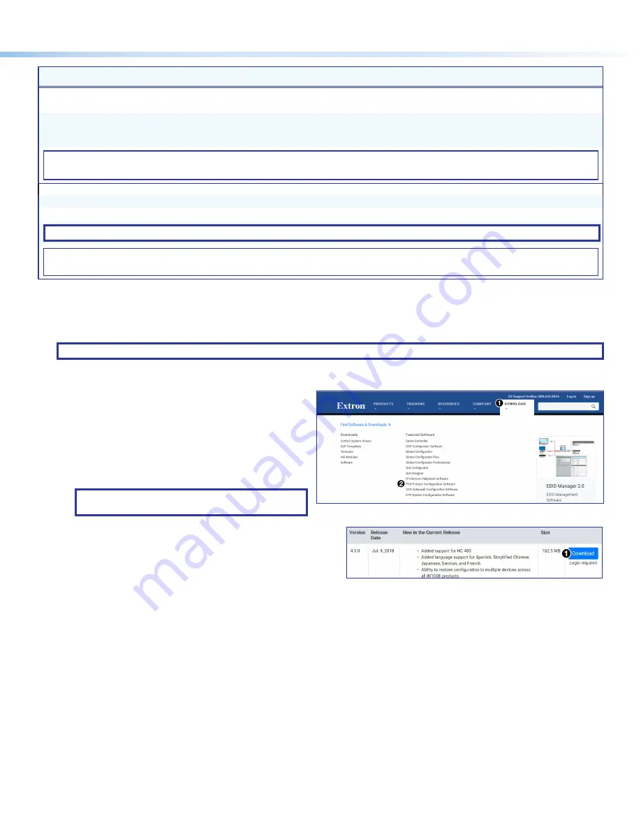
Download and install all programs as follows:
1.
Go to
Download
1
).
2.
Click the
PCS Product Configuration Software
link (
2
). The
PCS
Product
Configuration
Software
page opens.
3.
Click
Download
(see figure 8,
1
).
TIP:
Jump to the nearest page of downloads
by clicking the desired filtering letter.
Figure 7.
Download Drop-down List
The download warns about downloads and asks to confirm
the download.
4.
Click
Run
to confirm that you want to run the installation.
5.
Follow the on-screen instructions. The installation program
creates the necessary directories and folders and installs the
program.
Figure 8.
Download Center Dialog Box
7
8


