background image


9

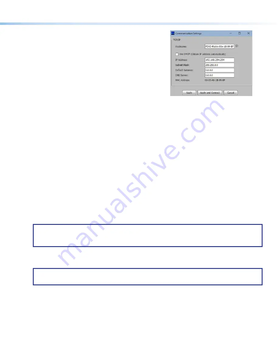
To edit the IP address:

1. 

Click on the 

Edit

 button (see 

figure 9

3

 on page 8). The 

Communication


Settings

 box opens.

2. 

Click in the field to edit (see figure 11) .

3. 

Click 

Apply

 to complete and close. 

Alternatively, click 

Apply


and


Connect

 to complete and connect to the 

device.
Click 

Cancel

 to close the box without changes.

Figure 11. 

Communication Settings Box

Internal Web Pages

Another way to configure and operate the switcher is via its factory-installed internal web pages. The pre-loaded web pages on 
the switcher are accessible through the LAN port (see 

figure 2

,

 C

 on page 2) via a LAN or WAN connection or the front panel 

USB config port (see 

figure 6

,

 A

 on page 4) using a web browser such as Microsoft

®

 Internet Explorer

®

.

Disabling Compatibility Mode

The internal web page does not support compatibility mode in Microsoft Internet Explorer.
To check compatibility view settings:

1. 

From the 

Tools

 menu of the browser, select 

Compatibility


View


Settings

. The 

Compatibility


View


Settings

 dialog box 

opens.

2. 

Be sure the 

Display


all


websites


in


Compatibility


View

 checkbox is clear, and the IP address of the matrix is not in the 

list of websites that have been added to 

Compatibility


View

.

Accessing the Internal Web Page

Access the FOX3 Matrix internal web page as follows:

1. 

Connect the FOX3 Matrix to a LAN or WAN using the rear panel RJ-45 LAN connector (see 

figure 2

,

 C

) or the front panel 

USB config port (see 

figure 6

,

 A

 on page 4).

2. 

Open a web browser on a connected PC.

3. 

Enter the FOX3 Matrix IP address in the browser 

Address

 field.

NOTES:

• 

If the local system administrators have not changed the value, the factory specified default for the LAN or WAN 
connection is 

192.168.254.254

.

• 

The default for the USB connection is 

203.0.113.22

 (this IP address cannot be changed).

4. 

Press the <

Enter

> key on the keyboard.

5. 

The FOX3 Matrix is password protected. Enter a user name (

user

 or 

admin

) in the 

Username

 field and the password in the 

Password

 field when prompted (see 

figure 12

 on page 10).

NOTE:

  The factory configured passwords for all accounts on this device have been set to the device serial number. In 

the event of a complete system reset, the passwords convert to the default. The default username is 

admin

 and the 

password is 

extron

.

11 


Summary of Contents for FOX3 Matrix 80x

Page 1: ... OUT IN 2 OUT IN 7 OUT IN 3 OUT IN 8 OUT IN 4 OUT IN FOX3 MATRIX 8io 5 OUT IN 1 OUT IN 6 OUT IN 2 OUT IN 7 OUT IN 3 OUT IN 8 OUT IN 4 OUT IN FOX3 MATRIX 8io 5 OUT IN 1 OUT IN 6 OUT IN 2 OUT IN 7 OUT IN 3 OUT IN 8 OUT IN 4 OUT IN FOX3 MATRIX 8io 5 OUT IN 1 OUT IN 6 OUT IN 2 OUT IN 7 OUT IN 3 OUT IN 8 OUT IN 4 OUT IN R 100 240V 0 7A MAX 50 60 Hz FOX3 R 301 HDMI LAN OUT A IN OUT IN B INPUTS CONTROL A...

Page 2: ... WARNING This unit outputs continuous invisible light which may be harmful to the eyes use with caution For additional safety plug the attached dust caps into the optical transceivers when the fiber cable is unplugged AVERTISSEMENT L appareil émet une lumière invisible en continu à utiliser avec précaution Pour une sécurité renforcée associez les bouchons anti poussière à l ensemble émetteur récep...

Page 3: ...ht cable Computer or control system connection Wire the interface cable as a crossover cable D Remote RS 232 port Optionally connect a control system or computer to the rear panel Remote RS 232 port see figure 3 for wiring RS 232 Tx Rx G REMOTE Transmit Receive Receive Transmit Ground Ground DB9 Pin Locations Female 5 1 9 6 Pin 2 Rx Pin 3 Tx Pin 5 G Computer Figure 3 RS 232 Connector Wiring E Rese...

Page 4: ...se two RJ 45 connections Fiber optic I O board LED indication On the fiber optic I O boards the input and output LEDs on the transceivers light green when 10G light is detected The arrow LEDs point to the input and output port they represent In figure 5 SFP 1 and SFP 5 are examples of the LEDs that indicate the input and output port different colors are used to indicate the connection only Out 1 i...

Page 5: ...002 002 003 003 Output switching NOTES The quick multiple tie and tie input to all output commands activate all I O switches simultaneously The tie command tie command and tie command can be used interchangeably The tie all command tie all command and tie all command can be used interchangeably When you create a tie where X 00 you tie no input to the specified output X untie X When you create a ti...

Page 6: ... 00 Maximum number of outputs for your configuration 00 untied Matrix Status Request Information I i Verbose mode 2 3 VX2 XX2 AX XX3 SX 1 X X 2 X n Inf00 VX2 XX2 AX XX3 SX 1 X X 2 X n Slot LC connector information 0 X I Verbose mode 2 3 X1 X1 X1 X1 X1 X1 X1 X1 Inf X1 X1 X1 X1 X1 X1 X1 X1 Request part number N n 60 nnnn nn View power supply voltages unit temperature fan speeds and Power Supply stat...

Page 7: ...r way to operate the switcher is via Product Configuration Software PCS which runs on computers that use the Windows operating system This program is available on the Extron website PCS can be run from a PC connected to the rear panel LAN port see figure 2 C or front panel configuration port see figure 6 A on page 4 on the switcher NOTE For details on operating PCS see the FOX3 Matrix 80x Help fil...

Page 8: ...r the TCP IP panel see figure 9 1 Open the Product Configuration Software program from the desktop shortcut The Extron PCS window opens to the Device Discovery panel see figure 9 Figure 9 Device Discovery Panel 2 Select the FOX3 Matrix 80x device by clicking on it to highlight it in the list 1 3 Click Connect 2 The FOX3 Matrix 80x PCS main page opens see figure 10 Figure 10 FOX3 Matrix 80x PCS Mai...

Page 9: ...he Display all websites in Compatibility View checkbox is clear and the IP address of the matrix is not in the list of websites that have been added to Compatibility View Accessing the Internal Web Page Access the FOX3 Matrix internal web page as follows 1 Connect the FOX3 Matrix to a LAN or WAN using the rear panel RJ 45 LAN connector see figure 2 C or the front panel USB config port see figure 6...

Page 10: ...12 Network Password Prompt 6 Click the Sign in button The internal web page opens see figure 13 Figure 13 Internal Web Main Page NOTE For detailed information about the internal web page see the FOX3 Matrix 80x User Guide available at www extron com ...

Page 11: ...al installation and subsequent access to the panel Les vis doivent être serrées avec un outil adapté après la première installation et l accès postérieur au panneau NOTES On a fiber optic I O module as delivered from Extron all transceiver modules are configured the same either all multimode or all singlemode Multimode and singlemode fiber optic I O modules can be mixed in a FOX3 matrix switcher b...

Page 12: ...enclosure until the power supply meets resistance 7 Gently seat the power supply in the backplane 8 Use a screwdriver to tighten the left and right captive panel screws to lock the power supply in place L R L R L R L R AU DIO EX PAN SIO N AT DM P EX PA NS ION LINK AU DIO OU TPU TS L R L R L R L R AU DIO INP UT SS 4 3 2 1 4 3 2 1 LINK FO X3 MA TR IX AU DIO DA NT E EX PA NS ION RE SE T Tx Rx G RS 23...

Reviews: