12
68-2987-50 Rev. B
03 20
For information on safety guidelines, regulatory compliances, EMI/EMF compatibility, accessibility, and related topics, see the
Extron Safety and Regulatory Compliance Guide
on the Extron website.
© 2020 Extron Electronics — All rights reserved.
All trademarks mentioned are the property of their respective owners.
Worldwide Headquarters:
Extron USA West, 1025 E. Ball Road, Anaheim, CA 92805, 800.633.9876
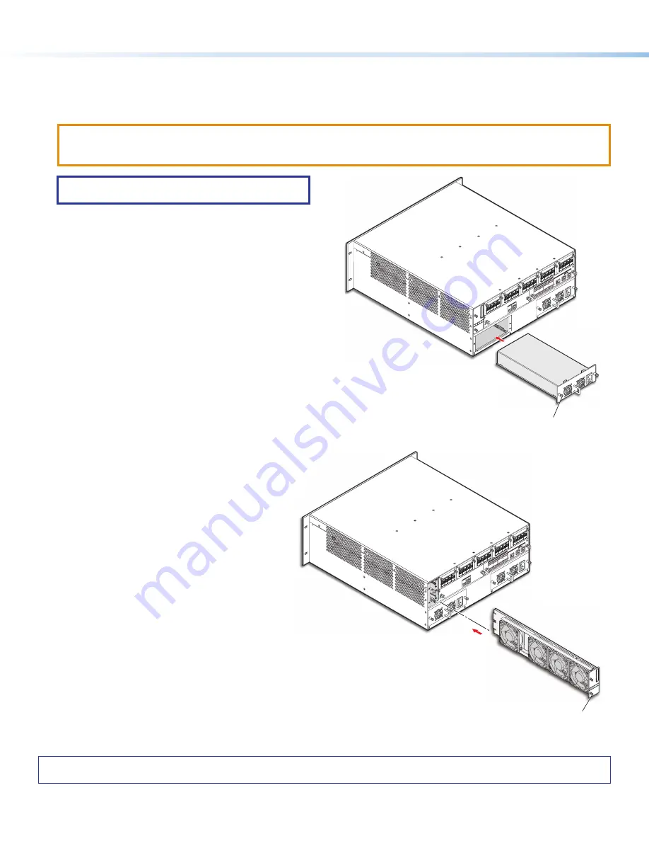
Removing and Installing a Power Supply Module
The two power supply modules (primary power supply and redundant power supply) are identical. Each power supply module has
a 2-color LED, visible on the front panel, that indicates the status of the power supply outputs. If the LED is lit green, the power
supply is operating normally. If the LED is lit red, the supply has failed and should be replaced at the earliest opportunity.
ATTENTION:
•
Disconnect both power supply cords before servicing.
•
Débranchez les deux câbles de la source d’alimentation avant l’entretient.
NOTE:
Power supply modules are not interchangeable
between other FOX3 Matrix models.
1.
Rotate the left and right captive panel screws to completely
loosen the screws (see figure 15).
2.
Gently pull on the handle to loosen the power supply from
the backplane.
3.
Slide the power supply out of the chassis.
4.
Orient the power supply module to be installed with handle
on the bottom.
5.
Align the flanges on the power supply module with the left
and right power supply guides.
6.
Gently slide the power supply module into the enclosure until
the power supply meets resistance.
7.
Gently seat the power supply in the backplane.
8.
Use a screwdriver to tighten the left and right captive panel
screws to lock the power supply in place.
L
R
L
R
L
R
L
R
AU
DIO
EXP
AN
SIO
N
AT
DM
P
EX
PA
NS
ION
LINK
AU
DIO
OU
TPU
TS
L
R
L
R
L
R
L
R
AU
DIO
INPU
TSS
4
3
2
1
4
3
2
1
LINK
FO
X3
MA
TR
IX
AU
DIO
DA
NTE EX
PA
NS
ION
RES
ET
Tx
Rx
G
RS
-23
2
REM
OT
E
LA
N
FA
N A
SS
EM
BLY
Extr
on
INPUTS / OUTPUT
S
1 - 40
1-8
9-1
6
17-
24
25-
32
33-
40
INP
UT/O
UTP
UT
LEG
EN
D
Captive Panel Screw
Figure 15.
Replacing a Power Supply
Removing and Installing a Fan Module
The FOX3 Matrix has a single fan module with multiple
fans. If the fan fails, it should be replaced at the
earliest opportunity.
1.
Rotate the top and bottom captive panel screws
to completely loosen the screws (see figure 16).
2.
Gently pull on the captive panel screws to loosen
the fan from the backplane.
3.
Slide the fan out of the chassis.
4.
Orient the replacement fan so that the printing on
the back of the panel is right-side up.
5.
Align the flanges on the fan with the top and
bottom fan guides.
6.
Gently slide the fan into the enclosure until the fan
meets resistance.
7.
Gently seat the fan in the backplane.
8.
Use a screwdriver to tighten the top and bottom
captive panel screws to lock the fan in place.
L
R
L
R
L
R
L
R
AU
DIO
EXP
AN
SIO
N
AT
DM
P
EX
PA
NS
ION
LINK
AU
DIO
OU
TPU
TS
L
R
L
R
L
R
L
R
AU
DIO
INPU
TSS
4
3
2
1
4
3
2
1
LINK
FO
X3
MA
TR
IX
AU
DIO
DA
NTE EX
PA
NS
ION
RES
ET
Tx
Rx
G
RS
-23
2
REM
OT
E
LA
N
FA
N A
SS
EM
BLY
Extr
on
INPUTS / OUTPUT
S
1 - 40
1-8
9-1
6
17-
24
25-
32
33-
40
INP
UT/O
UT
PU
T L
EGEN
D
Align with Plastic Guides
Captive Panel Screw
Figure 16.
Replacing a Fan
15
16


