background image

2-2

Refer also to the 

Fiber Matrix 6400 Switcher User’s Manual

 at www.extron.com.

Refer also to the 

Fiber Matrix 6400 Switcher User’s Manual

 at www.extron.com.

Rear Panel

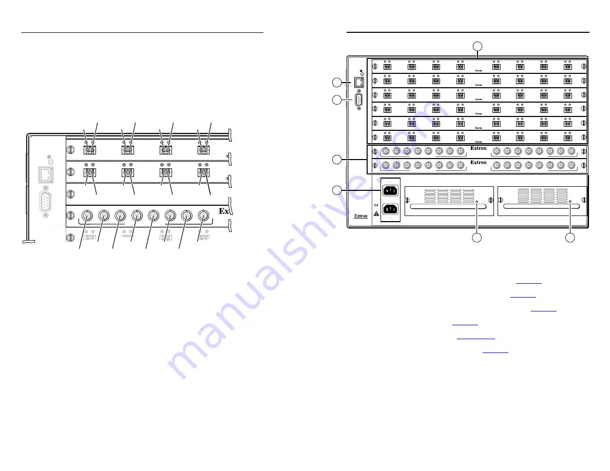
A note on I/O boards

See figure 2-2.  Each I/O board is identified by the input and 

output numbers supported by the board position (1 - 8, 9 - 16, 

and so on)  The transceiver modules on fiber optic I/O boards 

and the BNC connectors on SDI/HD-SDI boards are identified 

as A through H.

RESET

RS232/RS422

REMO

TE

LAN

A

CT

LINK

1 - 8

9 - 16

17 - 24

25 - 32

33 - 40

OUT

IN

A

OUT

IN

B

OUT

IN

C

OUT

IN

D

OUT

IN

A

OUT

IN

B

OUT

IN

C

OUT

IN

D

OUT

IN

OUT

IN

OUT

IN

OUT

IN

MUTI-RATE SDI INPUTS

H

G

A

D

E

F

C

B

Slot 1

Fiber optic

Inputs 1-8

Outputs 1-8

Output 1

Input 1

Slot 2

Fiber optic

Inputs 9-16

Outputs 9-16

Slot 3

No board

installed

Slot 4

SDI/HD-SDI

Inputs 25-32

Outputs 25-32

Output 2

Input 2

Output 3

Input 3

Output 4

Output 9

Output 10

Output 11

Output 12

Input 4

Input 25

Input 26

Input 27

Input 28

Input 29

Input 30

Input 31

Input 32

Input 9

Input 10

Input 11

Input 12

Figure 2-2 — Arrangement of inputs and outputs on 
the I/O boards

Locations A through H correspond to the input and output 

numbers identified by the board position numbers.  (For 

example, the input and output numbers supported by the 

I/O board in location 9 - 16 are as follows: A = 9, B = 10, C = 11, 

D = 12, E = 13, F = 14, G = 15, and H = 16.)
On the fiber optic I/O boards, locations A through H correspond 

to the transceiver modules, each of which includes an input and 

an output.  Therefore, locations A through H are numbered from 

left to right.
On the SDI/HD-SDI I/O boards, inputs and outputs are 

grouped separately, with inputs A through H on the left and 

outputs A through H on the right.

Figure 2-1 — Fiber Matrix 6400 Switcher 1616 rear 
panel

a


Fiber optic connectors and LEDs

 — See page 2-4.

b


SDI/HDI-SDI BNC connectors

 — See page 2-5.

c


Ethernet connection (LAN connector)

 — See page 2-5.

d


Remote port

 — See page 2-5.

e


Power connectors

 — See page 2-5.

f


Power indicator LEDs

 — See page 2-5.

ANAHEIM, CA

RESET

RS232/RS422

REMO

TE

LAN

A

CT

LINK

1 - 8

9 - 16

17 - 24

25 - 32

33 - 40

41 - 48

49 - 56

57 - 64

100-240V      50/60Hz

2A MAX.

100-240V      50/60Hz

2A MAX.

REDUNDANT

PRIMARY

PRIMARY POWER SUPPLY

REDUNDANT POWER SUPPLY

OUT

IN

A

OUT

IN

B

OUT

IN

C

OUT

IN

D

OUT

IN

E

OUT

IN

F

OUT

IN

G

OUT

IN

H

OUT

IN

A

OUT

IN

B

OUT

IN

C

OUT

IN

D

OUT

IN

E

OUT

IN

F

OUT

IN

G

OUT

IN

H

OUT

IN

A

OUT

IN

B

OUT

IN

C

OUT

IN

D

OUT

IN

E

OUT

IN

F

OUT

IN

G

OUT

IN

H

OUT

IN

A

OUT

IN

B

OUT

IN

C

OUT

IN

D

OUT

IN

E

OUT

IN

F

OUT

IN

G

OUT

IN

H

OUT

IN

A

OUT

IN

B

OUT

IN

C

OUT

IN

D

OUT

IN

E

OUT

IN

F

OUT

IN

G

OUT

IN

H

OUT

IN

A

OUT

IN

B

OUT

IN

C

OUT

IN

D

OUT

IN

E

OUT

IN

F

OUT

IN

G

OUT

IN

H

MUTI-RATE SDI INPUTS

H

G

A

D

E

F

C

B

MUTI-RATE SDI OUTPUTS

H

G

A

D

E

F

C

B

MUTI-RATE SDI INPUTS

H

G

A

D

E

F

C

B

MUTI-RATE SDI OUTPUTS

H

G

A

D

E

F

C

B

6

6

3

4

1

2

5

1

2

3

Fiber Matrix 6400 Switcher • Installation

Installation

Fiber Matrix 6400 Switcher • Installation


2-3

Summary of Contents for Fiber Matrix 6400

Page 1: ...33 453 4050 Extron Electronics Asia 135 Joo Seng Rd 04 01 PM Industrial Bldg Singapore 368363 800 7339 8766 65 6383 4400 FAX 65 6383 4664 Extron Electronics Japan Kyodo Building 16 Ichibancho Chiyoda...

Page 2: ...den Stromunterbrechung Um das Ger t auf sichere Weise vom Netz zu trennen sollten Sie alle Netzkabel aus der R ckseite des Ger tes aus der externen Stomversorgung falls dies m glich ist oder aus der W...

Page 3: ...ection against harmful interference when the equipment is operated in a commercial environment This equipment generates uses and can radiate radio frequency energy and if not installed and used in acc...

Page 4: ...or Recalling a Preset 3 3 Locking Out the Front Panel Executive Mode 3 3 Chapter Four Remote Control 4 1 Selected SIS Commands 4 2 Establishing a network Ethernet connection 4 2 Connection timeouts 4...

Page 5: ...er One Introduction About this Manual About the Fiber Matrix 6400 Switchers All trademarks mentioned in this manual are the properties of their respective owners 68 1371 50 Rev A 06 08 ii Fiber Matrix...

Page 6: ...Typical Fiber Matrix 6400 application The Extron proprietary fiber optic signal generated by FOX 500 transmitters can include video stereo audio and transmitter to receiver RS 232 serial communication...

Page 7: ...ptic transceiver modules SDI HD SDI 8x8 I O board equipped with permanent BNC connectors N As listed above two versions of the fiber optic I O boards are documented in this manual They are categorized...

Page 8: ...he fiber optic I O boards locations A through H correspond to the transceiver modules each of which includes an input and an output Therefore locations A through H are numbered from left to right On t...

Page 9: ...video inputs to these BNC connectors Multi rate SDI Output connectors Connect digital displays to these BNC connectors c Ethernet port If desired connect a network WAN or LAN hub a control system or...

Page 10: ...ion port g Configuration port If desired connect a control system or computer to the front panel Configuration RS 232 port Use an optional 9 pin D to 2 5 mm mini jack TRS RS 232 cable part 70 335 01 3...

Page 11: ...unlit state Saving or Recalling a Preset 1 Save a preset Press and hold the Preset button until it flashes PRESET PRESET Preset button blinks Press and hold 2 seconds Save a preset Recall a preset Pr...

Page 12: ...anual at www extron com 4 Chapter Four Remote Control Selected SIS Commands Installing and Starting the Control Program Accessing the HTML Pages Fiber Matrix 6400 Switcher Front Panel Operation Front...

Page 13: ...suing the Query Q command to keep the connection active or disconnecting the socket and reopening the connection when necessary Number of connections A switcher can have up to 200 simultaneous TCP con...

Page 14: ...d video output tie X X Video input X is tied to output X Read audio output tie X X Audio input X is tied to output X Command ASCII command host to switcher Response switcher to host Additional descrip...

Page 15: ...talled 0 No board installed 1 8x8 multimode board 2 8x8 singlemode board 3 SDI HD SDI board x Unknown board or mix of transceivers installed X Firmware version number to second decimal place x xx Comm...

Page 16: ...If the installation program does not self start run Launch exe from the CD 2 Click the Software tab 3 Scroll to the Matrix Switchers program and click Install 4 Follow the on screen instructions The...

Page 17: ...See c on page 2 5 for connection information Loading the start up page N If your Ethernet connection to the matrix switcher is unstable try turning off the proxy server in your Web browser In Microso...

Page 18: ...click OK 6 The switcher downloads the HTML start up page The switcher is ready for operation via HTML remote control 5 Chapter Five Maintenance and Modifications Removing and Installing an I O Board...

Page 19: ...or an I O board disconnect any connected cables 2 Rotate the left and right knurled knobs to completely loosen the captive screws 3 Gently pull on the knurled knobs captive screws to loosen the board...

Page 20: ...wer supply out of the chassis 4 Orient the power supply module to be installed with the LED to the right 5 Align the flanges on the power supply module with the left and right power supply guides see...

Page 21: ...Refer also to the Fiber Matrix 6400 Switcher User s Manual at www extron com Fiber Matrix 6400 Switcher Maintenance and Modifications Maintenance and Modifications cont d 5 6...

Reviews: