background image


TKG250 Ultrasonic Thickness Gauge 


53


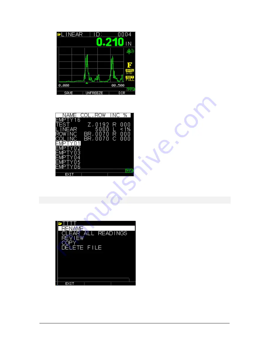
The following screen appears: 


2.


Use the up and down arrow keys to select the file you would like to rename and 
press the 

OK

 key.  

Note:

 The Rename option is not available for the first three factory default files. 

The following screen appears: 


3.


Use the up and down arrow keys to select the 

Rename

 option and press the 

OK


key to rename the file. 

Summary of Contents for TKG250

Page 1: ...USER GUIDE Model TKG250 Ultrasonic Thickness Gauge ...

Page 2: ...above is inclusive and no other warranty whether written or oral is expressed or implied The information in this document is subject to change without notice and describes only the product defined in the introduction of this documentation This document is intended for the use of Extech Instruments customers only a Flir Systems Inc brand for the purposes of the agreement under which the document is...

Page 3: ...el I 40 hour class room training in Ultrasonic Theory Flir Systems and any of its employees or representatives shall not be held responsible for improper use of this equipment for its intended use Proper training a complete understanding of Ultrasonic wave propagation thorough reading of this manual proper transducer selection correct zeroing of the transducer correct sound velocity proper test bl...

Page 4: ...tions 11 Power on the Gauge 11 Performing a Reset 12 Database Reset 12 Parameter Reset 13 Database Parameter Reset 14 Backlight 14 About Screen 15 3 Calibrating the Gauge and Making Measurements 16 Velocity Calibration Only 16 Velocity and Zero Calibration 17 Zero Calibration Only 17 Delay Line Calibration 17 Automatic Zero 18 Measurement Mode with a Datalogger 19 4 Adjusting parameters in A Scan ...

Page 5: ...irectory Mode 42 Managing the Datalogger File System 45 Creating a new File 47 Selecting a Custom Linear File 49 Selecting a Custom Grid File 49 Reviewing a File 50 Reviewing a Linear File 51 Reviewing a Grid File 52 Renaming a File 52 Clearing all readings within a File 55 Copying a File 56 Deleting a File 58 Waveform Adjustments 65 Blanking 69 8 Technical Specifications 72 Specifications for the...

Page 6: ...ability Gain boost Multiple dual and single element transducer options including high temperature The TKG250 offers a simple user interface packaged in a custom molded high density plastic case with rubber keypad This gauge offers reliable accurate thickness readings on mostly steel structures with access to only one side The TKG250 offers live color waveform A Scan The TKG250 provides a gain adju...

Page 7: ...is not coupled to the test piece when the gauge is first turned on and that there is no couplant on the end of the transducer The transducer should also be at room temperature clean without any noticeable wear For a more accurate span of calibration Flir Systems recommends a zero calibration and sound velocity calibration as well Upon first turning on the gauge you can match the transducer part nu...

Page 8: ... function that corresponds with the appropriate F key For example F1 may correspond with the Save function F2 with the Freeze function or F3 with the Directory function Dir Display Screen The gauge has a graphic style color TFT with 270x220 pixel density Viewing the screen is best from straight above or slightly below the surface rather than from side to side If external temperatures are below 32 ...

Page 9: ...ows the File name ID number AA and 0001 for grid column and row The lower part of the display acts as an interactive tool that allows you to decide how you want to proceed with the information that is displayed on the screen The middle part of the screen shows the thickness value In mm or usec Echo to Echo symbol LOS for loss of signal Freeze Fast Min or Max Alarm indicator Differential mode Low M...

Page 10: ...When the gauge gets below 10 the indicator will turn from green to red and a 5 it will flash Note You should power down the TKG250 to ensure any saved data is stored internally Replacing the Battery To replace the battery pack unscrew the battery door on the bottom of the gauge and slide out the two AA batteries Replace with two new AA batteries paying attention that both positive ends should be f...

Page 11: ...n screen also referred to as Home screen in the manual 4 Use the up and down arrow keys to select a transducer and press OK key Please note the transducer selection will automatically display the transducer last used prior to shut off The following default transducer choices are available USER 5 0MHz DC110 1 0MHz DC175 1 0MHz DK250 2 0MHz DC250 2 0MHz DK525 s 5 0MHz DC525 5 0MHz DK550 5 0MHz DC550...

Page 12: ...meter or Database Parameter option by using the up and down arrow keys and press the Menu Ok key to make a selection See the following sections to perform each of these reset options Database Reset Performing a Database Reset clears all the files in the database and keeps the first three Linear Row increment and Col increment database files with cleared readings All the user created files in the d...

Page 13: ...Parameter Reset restores default parameters to the factory settings To perform a Parameter Reset follow these steps 1 From the Home screen press the F1 Reset key The Reset screen appears 2 Select the Parameter option and press the OK key The following screen appears If you want to exit this screen press either the F1 Exit key or F3 No key to take no action and return to Home screen 3 Press the F2 ...

Page 14: ...e F1 Exit key or F3 No key to take no action and return to Home screen 3 Press the F2 Yes key to perform a Database Parameter reset After performing a Database Parameter Reset the Home screen appears automatically Backlight The backlight can be turned On or Off by pressing F3 Bklite Backlight can also be turned On Off or set on Auto using the Bklight option in the Setup Menu Display Menu The Wave ...

Page 15: ...on number and contact information from the gauge s About screen To go to the About Screen follow these steps 1 From the Home screen press the F1 Reset key The following Reset screen appears 2 Press the F3 About key The About screen appears showing company contact information 3 Press the F1 Exit key to return back to Reset selection screen ...

Page 16: ...he unknown material by measuring the time of flight from main bang to the first back echo By using the known thickness you can calculate velocity of the sound for the unknown material To perform any calibration first go to the measure mode and press Menu OK Then go to the Cal option in the Menu screen and press OK The following Cal mode screen should appear To exit the cal screen without performin...

Page 17: ...asuring the time of flight from main bang to the first back echo for the thinner step The calibrated zero is the calculated zero minus the measured zero To accurately measure a thickness of unknown material you need to know the velocity of the sound in the unknown material and the errors introduced by the cable and electronics This is called delay line and zero calibrated value for the transducer ...

Page 18: ...phic on the display screen 2 After three seconds the gauge automatically begins to zero the transducer During the delay line calibration a screen appears displaying the message Performing Auto Zero 3 A warning message will appear on the display screen if the delay line is below the acceptable limit for accurate thickness measurements You will need to replace the transducer or select the F1 key to ...

Page 19: ...ill look like the screen below To continue in Measurement mode follow these steps 1 Press the F1 key to select the Save option See Save section for datalogger version 2 Press the F2 key to select the Freeze option See Freeze section 3 Press the F3 key to select the Dir Directory option See Directory section 4 Press the Menu OK key to select the Menu option See Menu section ...

Page 20: ...ameter use either the right or left arrow until the parameter to be adjusted is highlighted Use the up or down arrow to adjust the parameter You can also view the functions for each parameter by pressing the Menu OK key When finished adjusting the parameter press the F1 done key set up for left hand user F3 for right hand user For gain control F2 AGC or Automatic Gain Conrol When in AGC the gauge ...

Page 21: ...hted Gain Highlighted NOTE Pay close attention when turning on Echo to Echo as thickness readings will not be accurate with Echo to Echo on versus off if you do not re calibrate You will also see an Echo to Echo cursor on the bottom of the screen to indicate where the measurements are being made ...

Page 22: ...on the Gauge The following modes are available To select Measurement mode follow these steps 1 Press Menu OK to get to Measurement mode 2 Use the up and down arrow keys to select the Measurement option and press the OK key The following Setup choices are available ...

Page 23: ... key indicated in the top right hand of the display screen to change the setting of the highlighted parameter The entire list of available Measurement parameters are as follows Note Hold is off screen in the above image Here is a list of what is under the Measurement Screen RANGE 00 500 RECT Full VEL 0 23300 IN US XDUCER DK537EE 5MH ZOOM OFF ALARM OFF BSCAN OFF DIFF OFF E TO E OFF FAST OFF GAIN 32...

Page 24: ...up and down arrows then use the left or right arrow to toggle through the color choices of Red green blue yellow white black grey light grey By varying the colors you can optimize ease of visibility and improve contrast The Wave is readable in direct sunlight as well as in doors It is highly recommended to use the back light set to on or auto when using the wave indoors You can not make two colors...

Page 25: ...ock setup screen might look like depending on the previous setup To change the Time Format select TIME FMT using up down arrow keys Use the left right arrow keys to select between 12 HR and 24 HR options 2 To change the Date Format select DATE FMT using up down arrow keys Use the left right arrow keys to select between MM DD and DD MM options 3 To set Minute select the MINUTE option using up down ...

Page 26: ...ing an LOS Reading LOS Loss of Signal occurs when the gauge is not making a valid reading for a variety of reasons This may be because there is not enough couplant the surface is too rough or rusty the transducer is low in sensitivity the temperature is too high there is a disbond between the coating and the steel or for a variety of other reasons In the event you try to save a reading in LOS with...

Page 27: ...d in the top right corner of the display screen The following parameters are available 2 Use the up and down arrow keys to select the desired parameter and press the OK key 3 Press OK key again to accept and return to Measure mode In the Measure mode in either the Datalogger or Non datalogger version of the gauge the selected Fast option setting is displayed under the thickness reading as shown in...

Page 28: ...Max is selected BLANK when Off is selected The Fast option allows you to select fast updates of measurements at 20 Hz compared to 4 Hz If you selected the FastMax option the LOS will display the LAST MAX measured value or if you selected the FastMin parameter the LOS will display the LAST MIN measured value If you select the On parameter from the Fast option the LOS will work normally and not show...

Page 29: ...T MIN measured value press the OK Menu key Using the Gain Option From the Measurement Screen gain refers to an increase in signal power echo height and is typically measured in decibels dBs The Gain function is useful for setting a reference level where by making it easier to add or subtract gain There are several types of gain Auto in three Gain options and Manual gain adjustment in 1dB steps ...

Page 30: ...on gauge the F3 key allows you to select the Gain option directly without having to go to through the Measurements Setup mode In the datalogger version F3 becomes Dir Directory 1 Use the up and down arrow keys in the Measurement screen to highlight the Gain option and press the OK key The following Gain parameters are available 2 Use the up and down arrow keys to select the desired Gain option 3 P...

Page 31: ...e displayed reading is less than the low alarm reference value High Alarm Audible alarm will occur when the displayed reading is higher than the high alarm reference value High_Low Alarm Audible alarm will occur and display will flash when the displayed reading is less than the low alarm or greater than the High alarm reference value Low Alarm Vibra Vibration alarm will occur and display will flas...

Page 32: ...Extech Instruments 32 TKG250 EN V2 4 11 13 Green echoes good Red echoes tripped alarm The Alarm option is available from the Measurement screen ...

Page 33: ... are using the non datalogger version you can also press the F1 Alarm key to go directly to the Alarm option without having to go through the Setup Mode The following ALARM selections are available 2 Use the up and down arrow keys to select the desired alarm parameters and press the OK key For example when you select the High Low option the following screen below appears Use the up and down arrow ...

Page 34: ...he Alarm Low settings 4 Setting the for caution In this mode the entered based on the high and low set points will cause the waveform and F2 to light up yellow Note The Low Alarm limit will not go beyond the High Alarm limit 5 When you are finished adjusting the setting press the OK key to return to Measure mode ...

Page 35: ...above the low value of 0 101 and 0 120 will result in the yellow F2 keypad lighting up as you are approaching the minimum So in Alarm mode choosing a non zero percent value provides the user with warning for readings approaching the selected percent value of the high or low limits For example if the alarm value is 0 100 and 20 is entered as the percent value reading from 0 101 to 0 120 will result...

Page 36: ...to make measurements between two consecutive backwall echoes Therefore a good usage of the Echo to Echo option is for measuring through coatings to measure only the true metal thickness There are two Echo to Echo options you can select which are as follows Echo to Echo On Enables the Echo to Echo function Echo to Echo Off Disables the Echo to Echo function Blanking in Echo to Echo close attention ...

Page 37: ...TKG250 Ultrasonic Thickness Gauge 37 Rectification Mode Adjustments Lastly in Echo to Echo sometimes using various rectification modes can clean up the signals so you are reading the proper echoes ...

Page 38: ... 13 The first Read line on the baseline is referred to as the Main Bang Blank while the second red line is referred to as the Blank After First Received echo The white line represents the measured time interval between the two correct echoes ...

Page 39: ... appear over either the F1 or F3 keys depending on how the user prefers to setup the gauge See section To use the Save option follow this step 1 From the Measurement mode screen press F1 Save Please note if the user has been set to righty under the Display Screen the Save will appear over the F3 key Note Save is on the left Note Save is on the right The data saved will depend on your setup paramet...

Page 40: ...ze The following screen comes up after pressing F2 Freeze whereby showing the flag Freeze under the thickness reading You are now in Freeze mode The F2 selection also changes from Freeze to Unfreeze 2 Press F1 Save to save the reading See Using the Save Option for more information 3 Press F2 Unfreeze to disable the Freeze mode 4 Press F3 Dir to perform file operations See Using the Directory Optio...

Page 41: ...TKG250 Ultrasonic Thickness Gauge 41 ...

Page 42: ...Directory Mode To use the datalogger Directory mode follow these steps You can either press F3 if Min or Max clear is not present or press the Menu OK key and view this screen Then you will see this screen Choosing a file Naming a file type in name press F3 when done ...

Page 43: ...ext you will need to use the up and down keys to determine the file type and amount of readings stored per file The many types are shown here You will also need to decide per file if you want to save thickness and a scan as per below screen ...

Page 44: ...5 000 and 160 A Scan The gauge will dynamically re calculate the size based on row end times column end 1 From the Measurement mode screen press F3 Dir to select the Directory mode By pressing Menu OK and choosing datalogger or F3 Dir you will be able to review create delete select rename and clear stored thickness and copy 2 Use the up and down arrow keys to view the list of files and select whic...

Page 45: ...e files are factory default files available for you to start storing thickness reading or make a quick copy of the file structure Linear or Grid Col Row in order to start saving data in the new file See File System for more information Managing the Datalogger File System The TKG250 supports the following two files types Linear file Consists of ID from 0001 to 5000 The extended memory option consis...

Page 46: ...6 then AF 1 to AF 156 If a new GRID file with END COLUMN ZZ then the maximum ROW you can slew up to is limited to 5000 26 for A to Z 26 26 for AA to ZZ 7 A 1 to A 7 then B 1 to B 7 then Z 1 to Z 7 then AA 1 to AA 7 then AB 1 to AB 7 then AZ 1 to AZ 7 then BA 1 to BA 7 then BB 1 to BB 7 then ZZ 1 to ZZ 7 Note There are a few different types of Grid file 2D 3D and boiler The above two examples show ...

Page 47: ...ents as follows A 1 to ZZ 1 then A 2 to ZZ 2 then A 7 to ZZ 7 Creating a new File To create a custom file in the datalogger follow these steps 1 Press F3 Dir from the Measurement mode screen The following screen appears 2 Use the up and down arrow keys to highlight the next Empty file in the list ...

Page 48: ...he OK key to accept the selected characters If you make an error press F2 Del to delete the last character of the entered filename 5 Press F3 Done when you are finished entering the filename The following screen appears 6 Use the left and right arrow keys to select a file type LINEAR ROWINC or COLINC See the next two sections for more information on selecting file type for the new file ...

Page 49: ...o save THK only or THK Ascan by highlighting SAVE and using left or right arrows Use the up and down arrow keys to highlight the Start Column Now press left or right arrow key to change the value Note the F2 key will toggle between alpha and numbers so if you want to change A to 1 press F2 Then press down arrow key to select END COL option Press left or right arrow key to change the END COL value ...

Page 50: ... and END COL values press F3 Done The display will go back to Measure mode showing the new filename and next ID location in the top row as shown below Reviewing a File To review a file from the Measurement mode screen follow these steps 1 Press F3 Dir from the Measurement mode screen ...

Page 51: ...ilable The three factory default files have only 3 options Clear File Review and Copy Custom files have 5 options Rename Clear File Review Copy and Delete Select the Review option and press the OK key to review the file Reviewing a Linear File The linear file shows the ID and the stored readings along with the units You can browse the readings by pressing the up or down arrow key You can also pres...

Page 52: ...ey Then press OK to go to the measure mode When you have the new reading to be stored in the emptied file location press F1 Save The new reading will be saved in that location and the display will show the next empty file location in the top right corner Reviewing a Grid File The grid file shows the ID as COL ROW and the stored reading with the units F2 and F3 function keys operate in the same way...

Page 53: ... arrow keys to select the file you would like to rename and press the OK key Note The Rename option is not available for the first three factory default files The following screen appears 3 Use the up and down arrow keys to select the Rename option and press the OK key to rename the file ...

Page 54: ...ilename 5 Press F3 Done when you are finished entering the filename The old filename will be updated with the new filename in the directory as shown in the example below Note Press F1 Exit to exit the screen without renaming the file Example A user erases a file named ABCD by pressing F2 Del and selects XYZ as the new filename and presses F3 Done to accept the entered new filename The old filename...

Page 55: ...ing a File section To clear all the readings from a file but keep the file structure with id still available use the clear all readings To do this from measurement mode press F3 Dir for the Directory mode The following screen appears 1 Use the up and down arrow keys to select the file you want to clear and press the OK key The following screen appears ...

Page 56: ...rmation prompt appears Press F1 Exit to exit without clearing the thickness readings Press F2 Yes to clear the stored thickness from the entire file Press F3 No to exit without clearing the thickness readings If the file is already clear the unit will show NO READINGS TO CLEAR message Copying a File To copy a file from the Measurement mode screen follow these steps 1 Press F3 Dir for the Directory...

Page 57: ...file structure factory default or custom can be copied Note When you copy a file only the structure of the file ID is copied and not the associated file readings 3 Use the up and down arrow keys to select the Copy option and press the OK key The following confirmation prompt appears with the next Empty file highlighted as the default choice ...

Page 58: ... to accept the selected characters If you make an error press F2 Del to erase last character before the cursor 5 Press F1 Exit to exit without copying the file 6 Press F3 Done when you are finished entering the filename A new file with the selected name will be added in the directory with the file structure of the original file ABCD Deleting a File To delete a file from the Measurement mode screen...

Page 59: ... and down arrow keys to select the file to be deleted and press the OK key Note Only custom files can be deleted The factory default files cannot be deleted 3 Use the up and down arrow keys to select the Delete option and press the OK key The following confirmation prompt appears ...

Page 60: ...e allows the operator to compare 2 files to one another As an example a file taken 6 months ago can be compared to the same file taken today First set up a new file or if available copy the file to be compared to and assign a new name Clear out the readings of the old file prev while in the new file curr Press Menu OK then Diff for differential as the new file will be a differential to the old fil...

Page 61: ...TKG250 Ultrasonic Thickness Gauge 61 File compare with absolute once chosen files of like structure appear File compare ...

Page 62: ...to alarm on compared file where the gauge will prompt you to enter either a or absolute reading for wall loss or growth based on the change at the same id of the current file to the previous file Growth although not very common can mean either a bad previous reading scale build up or temp change affecting sound velocity on a previous reading In the alarm file compare screen you can even enable the...

Page 63: ... the ID location Linear Row Col with notes To change the Notes settings select the Notes option from the Datalogger screen In versions 1 7 or higher notes can be set to the following Off Always or LOS or loss of signal Off is always off when save is pressed no notes appear Always is always on therefore when save is pressed the list of notes appears On LOS only when save is pressed without a valid ...

Page 64: ... note will be stored at the ID location and based on the file type Linear Row or Col is incremented See Directory selection for file type details When save is pressed with notes on the gauge will display the following pick list and save a note with the i d currently on the screen After downloading the file to data xl interface program the note will appear with a particular set up number at the end...

Page 65: ...d tube RIBB Waveform Adjustments To adjust any of the above settings from the main measurement screen simply use the left right up or down arrow until the desired parameter is highlighted In other words the arrow keys will act as a mouse or cursor to highlight the desired parameter As an example if the right arrow unit Rectify is highlighted then press Menu OK to adjust the rectification mode by a...

Page 66: ...at a steel velocity Here are a couple of pictures at 100 and 4 000 inches Zoom prompt rangle at 286 100 echo centered on screen inch echo centered on screen right of screen minus left of screen equals range 28 The TKG250 has a live Color Waveform with Adjustments Only operators familiar with detailed Ultrasonic knowledge and training should adjust waveform related functions see liability statement...

Page 67: ... alert the operator of an alarm condition as such Good readings in green Tripped alarm in Red Caution of high or low detected Large Thickness Reading F3 RF signal with cursor upside down V indicating where the measurement is being made Example of Echo to Echo with blanking ...

Page 68: ...0 and 20 inches or 12 7 25 4 125 254 and 500 mm To select the Auto Zoom tracking use the left or right arrow key until range bottom right is hightlighted and then the up and down arrow keys to select the desired range You can also enable zoom from the Menu OK key choose Measurement range and adjust to zoom Note if you are measuring a 2 inch part with a 1 range no echoes will be visible Please adju...

Page 69: ...n Rectify RF Full Wave Half and Half Use the left or right arrow keys to highlight RECT for rectify the up or down arrows to select between RF Full Wave Half Wave or Half Wave The default setting is Full Wave Rectified Blanking To adjust for main bang blank or blank after first received echo Use the arrow keys to highlight Blanking select main bang blank or blank after first received echo in Echo ...

Page 70: ...s the arrow keys will act as a mouse or cursor to highlight the desired parameter As an example if the right arrow unit Rectify is highlighted then press Menu OK to adjust the rectification mode by again using the right or left key to except press F1 exit You can follow the same procedure for Gain Blanking and Range A newer feature in versions 1 7 or higher is the ability to show the thickness val...

Page 71: ...TKG250 Ultrasonic Thickness Gauge 71 F1 F3 ...

Page 72: ...alibration units freeze unfreeze battery life remaining gain low std high echo to echo symbol Resolution 0 001 0 01 mm 0 01 0 1mm Accuracy Basic Accuracy is 0 004 but on clean smooth steel an accuracy of 0 001 is not uncommon The more corrosive the environment and pitted the surface under test the closer to the 0 004 accuracy one can expect to be As noted a higher accuracy can be obtained when mea...

Page 73: ...ent Pending Backlight Light Emitting Diode On Off or Auto On based on valid readings or last key press Shut off Auto time out after 1 31 minutes user programmable after no reading loss or no key press or never Scan mode Simultaneously Displays minimum or maximum thickness value at 20 measurements per second ideal for high temperature thickness reading and tracking the minimum depth alarm Press Fre...

Page 74: ... think part with coating then MENU OK B Scan The B Scan represents a cross sectional view on the test piece The simplest example is to show a 5 step test block To turn on the option B Scan press MENU OK go to Measurement find B scan and press MENU OK First enter the maximum thickness you expect to scan using the up down left and right keys then turn on the B Scan scrolling down and right arrow lef...

Page 75: ...roximately 200 data points and a thickness and waveform file would be full before one B Scan full screen is complete Press done press F2 start and F1 Save You can now press menu OK scroll to Datalogger choose the B Scan file to review Menu OK Review Menu OK scroll over where an id and reading are present and press Menu OK the B scan will appear F2 will center the minimum min in the middle of the s...

Page 76: ...cal assistance or troubleshooting questions See below Calibration Repair and Customer Care Services FLIR Systems Inc offers repair and calibration services for the Extech Instruments products we sell NIST certification for most products is also provided Call the Customer Service Department for information on calibration services available for this product Annual calibrations should be performed to...

Page 77: ...ès vente FLIR Systems Inc offre des services de calibrage et de réparation pour les produits Extech Instruments que nous commercialisons Nous fournissons également une certification NIST pour la plupart des produits Contactez notre service client pour toute information sur les services de calibrage disponibles pour ce produit Un calibrage doit être effectué chaque année pour vérifier les performan...

Page 78: ... Soporte Técnico y servicios generales al cliente consulte la información de contacto en seguida Líneas de soporte EE UU 877 439 8324 Internacional 1 603 324 7800 Soporte Técnico Opción 3 correo electrónico support extech com Reparación Devoluciones Opción 4 correo electrónico repair extech com Las especificaciones del producto están sujetas a cambios sin aviso Por favor visite nuestra página en I...

Reviews: