Page
4
ML442 | v5k
Expo Technologies UK
T: +44 (0) 20 8398 8011
Expo Technologies US
T: +1 (440) 247 5314
Expo Technologies China
T: +86 532 8906 9858
3. Description and Principle of Operation
All Expo Technologies MiniPurge
pressurization systems provide:
a) a method of pressurizing a Pressurized Enclosure (PE) while at the same time compensating
for any leakage, together with
b) a method of purging the enclosure, before power is applied, to remove any flammable gas
that may have entered the enclosure while it was not pressurized,
c) visual indication of the MiniPurge
system status, and
d) an output to provide remote indication or control.
The MiniPurge
system comprises a number of component units. The units required depend on
the type of system selected. These are summarised in Table 1. The general description and
function of each is as follows:
3.1 Control Unit (CU)
The Control Unit (CU) is the heart of the system. It contains a pneumatic logic circuit specially
designed and built to control the functions required for purge and pressurization. For all systems
this includes air filtration, pressure and purge flow measurement, purge timing, and local visual
indication of Pressurized/Alarm and flow sensed. It also provides the outputs for power and
remote alarm control corresponding to the output type selected.
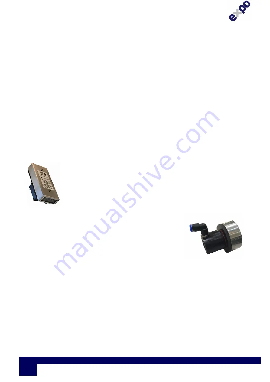
3.2 Relief Valve (RLV)
The Relief Valve unit is fitted to the PE to provide a means of limiting the
maximum pressure experienced by the PE during operation. The RLV
model number has a suffix giving the diameter of the valve aperture in
millimetres e.g. RLV25 (= 25mm bore). The RLV also incorporates a
Spark Arrestor to prevent sparks being ejected from the PE into the
classified area.
In Leakage Compensation systems, the RLV is combined with the flow
measurement mechanism.
Figure 1. LC Relief Valve
3.3 Calibrated Outlet Orifice/Spark Arrestor (SAU)
Continuous Flow systems incorporate the SAU25. This unit has a
range of interchangeable calibrated orifice plates, which are used
to measure the flow through the PE.
Figure 2 Spark Arrestor Type SAU25
3.4 The Methods of Pressurizing
a) CF - Continuous Flow
A Continuous Flow (CF) of protective gas is passed through the PE. Initially this flow is verified
and performs the purging phase of the operation. When the purging phase is completed – i.e.
the purge time has elapsed- the same flow of protective gas maintains the pressurization of the
enclosure. This flow may be required to dilute an internal source of hazardous gas release.


