ML358 v7
Page 1 of 1
18-Feb-16
MiniPurge Interface Unit MIU/e
User Instruction Manual
Manufacturer:
Expo Technologies Ltd
, Unit 2 The Summit, Sunbury on Thames. UK.
Model Type & Rating:
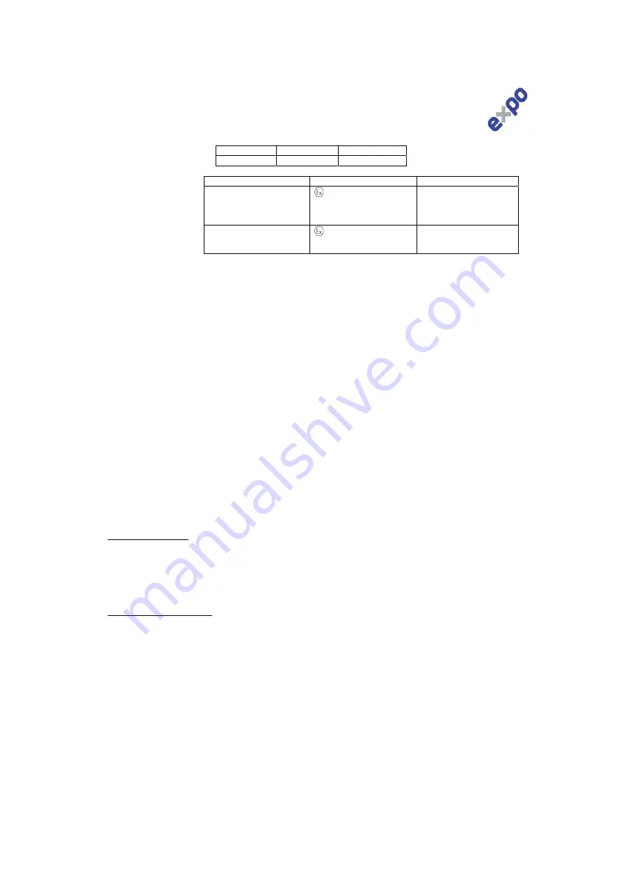
Certificates:
Hazardous Area Marking
Code:
APPLICATION SUITABILITY
The MiniPurge Interface Units – MIU/e are certified for use in Hazardous Areas where the Hazardous Area is non-mining
(i.e. above ground) and the hazard is caused by flammable gasses or vapours.
The systems may be used in ATEX/IECEx Gas Zones 1 & 2, Gas Groups IIA, IIB & IIC and in Dust Zones 21 & 22, Dust
Groups IIIA, IIIB & IIIC.
The following materials are used in the construction of MIU/e: Stainless Steel, Steel, Brass, Copper, Polyamide, Silicone.
If substances that will adversely affect any of these materials are present in the surrounding environment, please consult
Expo Technologies for further guidance. This equipment is designed for use under normal industrial conditions of ambient
temperature, humidity and vibration. Please consult Expo Technologies before installing this equipment in conditions that
may cause stresses beyond normal industrial conditions.
WARNING - Only install, commission, inspect, maintain or fault find when safe to do so.
INSTALLATION
The MIU/e shall be installed in accordance with relevant standards, such as EN 60079-14 and any local codes of practice
that are in force. Cable glands or other cable entry devices shall be appropriately certified and suitable for the cable and
the conditions of use and be installed in accordance with the manufacturer’s instructions.
The MIU/e shall be connected to the Purge and Pressurization system in accordance with the instructions given in the
handbook supplied with the pressurization system.
The external earth connection of the MIU/e shall be connected to earth using minimum 4mm
2
conductor.
TERMINALS
MIU/e may be fitted with a combination of:
WDU2.5 terminals certified to KEMA 98ATEX1683U & IECEx ULD05.0008U
SAK2.5 terminals certified to KEMA 98ATEX1798U & IECEx KEM06.0014U
WPE2.5 Earth terminals certified to KEMA 98ATEX1683U & IECEx ULD05.0008U
For all type of terminals:
Tightening torque range: 0.4 to 0.8 Nm (WDU & WPE) & 0.4 to 0.6 Nm (SAK)
Conductor cross section maximum 2.5 mm
2
, minimum 1.5 mm
2
Type of connection is screwed - Solid copper conductors to be used.
Stripping length shall be 10 mm.
Only one conductor is allowed at each side of a terminal. Multiple conductors shall be crimped together before screwed
into the terminal.
Maximum number of terminals:
For Model MIU/e1 – Up to 18 current carrying terminals
For Model MIU/e2 – Up to 33 current carrying terminals
For Model MIU/e1/MO – Up to 13 current carrying terminals
COMMISSIONING
The installation of the cable glands, electrical and earth connections shall be inspected for correct installation before the
unit is put into service. The lid shall be correctly fitted.
MAINTENANCE
The condition of enclosure and associated cable glands shall be inspected for damage every six months. The terminals
shall be inspected for tightness and gaskets inspected for damage.
FAULT FINDING
When wiring or signal fault occurs, check each terminated wire, terminals for tightness and gaskets for damage.
External faults such as broken switches within the Control Unit may also require investigation.
MIU/e1
MIU/e2
MIU/e1/MO
400V / 7A
400V / 7A
400 V / 2A
IECEx ITS10.0003X
ITS 10ATEX37092X
TUV 12.1463
Ex e IIC T5 Gb
Ex tb IIIC T100°C Db IP66
Tamb -20°C to +55°C
II 2 G D
Ex e IIC T5 Gb
Ex tb IIIC T100°C Db IP66
Tamb -20°C to +55°C
Ex e IIC T5 Gb
Ex tb IIIC T100ºC Db IP66
Tamb -20°C to +55°C
Ex e IIC T4 Gb
Tamb -20ºC to +60ºC
II 2 G D
Ex e IIC T4 Gb
Tamb -20°C to +60°C
Ex e IIC T4 Gb
Tamb -20°C to +60°C


