Maintenance
g240665
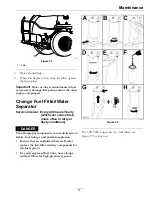
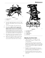
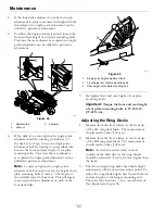
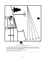
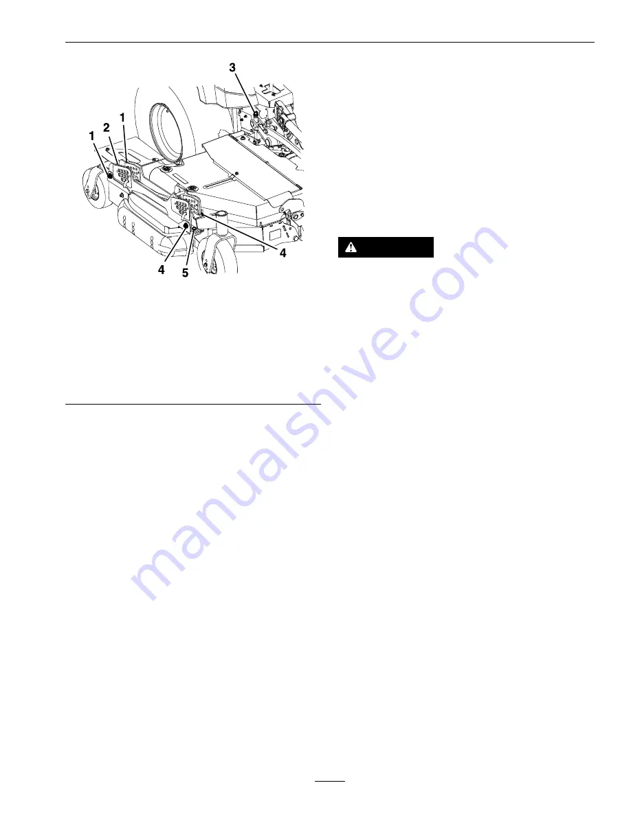
Figure 51
RH Wing Deck Shown
1.
Rear hanger mounting nuts
2.
Rear height adjustment hardware location
3.
Single point rear adjustment
4.
Front hanger mounting nuts
5.
Front height adjustment hardware location
•
If the deck is too low, tighten the front height
adjustment bolt (item 5, Figure 51) by rotating
the bottom nut clockwise.
•
If the deck is too high, loosen the front height
adjustment bolt (item 5, Figure 51) by rotating
the bottom nut counterclockwise. Fine tuned
the rear adjusters as required.
Adjust the rear wheel height (item 2, Figure 51)
so that the rear wheel lightly touches the ground
with minimal pressure.
4.
Measure the back of the wing blades. If either
has less than 1/16 inch (1.5 mm) rake, raise the
back of the deck by tightening the LH and RH
rear adjustments (item 3, Figure 51) until all
four blades have a minimum of 1/16 inch rake
(1.5 mm). Readjust the wing rear wheels so they
lightly touch the ground with minimal pressure.
Tighten all four rear hanger mount points (item
1, Figure 51).
5.
Retighten the front and rear height of cut hanger
jam nuts.
Deck Belt Tension
Self-tensioning - No adjustment necessary.
Parking Brake Adjustment
Service Interval: After the first 100 hours
Every 400 hours thereafter
Check to make sure brake is adjusted properly. This
procedure must be followed after the first 100 hours
or when a brake component has been removed or
replaced.
CAUTION
Raising the mower deck for service or
maintenance relying solely on mechanical
or hydraulic jacks could be dangerous. The
mechanical or hydraulic jacks may not be enough
support or may malfunction allowing the unit to
fall, which could cause injury.
Do Not rely solely on mechanical or hydraulic
jacks for support. Use adequate jack stands or
equivalent support.
1.
Drive the machine onto a level surface.
2.
Disengage the blade control switch (PTO), move
the motion control levers to the neutral locked
position and engage the parking brake (lever is in
the “up” position).
3.
Stop the engine, wait for all moving parts to stop,
and remove the key.
4.
Raise the back of the machine up and support the
machine with jack stands.
5.
Remove the rear tires from the machine.
6.
Remove any debris from the brake area.
7.
Rotate the drive wheel release handle to the
“released” position. Refer to the
Drive Wheel
Release Valves
section in Operation.
8.
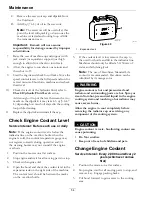
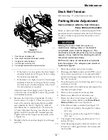
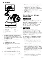
If the link assembly is attached (see Figure 52)
•
in the front position, the length=8.63 inches
(21.9 cm).
•
in the rear position, the length=9.15 inches
(23.2 cm).
9.
The length of the spring should measure 3 1/4
inches (8.3 cm).
10.
Once the spring length is achieved, check to see
if there is a visible gap between the trunion and
the shoulder.
61

