Operation
mm) clearance to the ground to minimize gouging
and roller wear or damage.
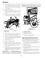
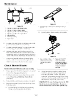
g035118
Figure 19
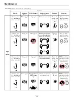
For cutting heights above 3.5 inches (90 mm) use the
bottom hole. The rollers will still be effective against
scalping.
1.
Anti-scalp roller
mounting bracket
2.
Cutting height
For Maximum Deck Flotation,
place the rollers
one hole position lower. Rollers should maintain
1/4 inch (6.4 mm) clearance to the ground.
Do
Not
adjust the rollers to support the deck.
7.
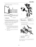
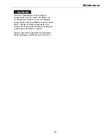
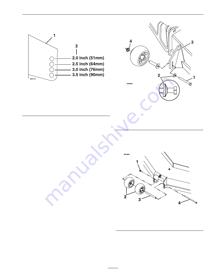
Reinstall the mounting hardware:
•
Side Discharge Models:
A.
Be sure the roller bolts are installed with
the spring disc washer between the head
of the bolt and the mounting bracket (see
Figure 20).
B.
Torque the 3/8 nyloc nut to 50–55 ft-lb
(68-75 N-m).
g023992
Figure 20
1.
3/8-16 X 3 3/4 Grade 8
bolt
3.
Front right anti-scalp
bracket shown
2.
Spring disc washer
(cone towards bolt head)
4.
3/8 nyloc-torque to 50-55
ft-lb (68-75 N-m)
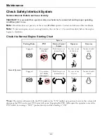
•
Rear Discharge Models:
Torque the 3/8 nyloc nut to 30-35 ft-lb (41-47
N-m) (see Figure 21).
g018862
Figure 21
1.
3/8 nyloc-torque to 30-35
ft-lb (41-47 N-m)
3.
Spacer
2.
Anti-scalp rollers
4.
Bolt
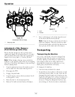
The 96 inch deck has 13 anti-scalp roller locations to
adjust see Figure 22.
35


