Operation
information, reset counters, modify system settings,
and troubleshoot the equipment.
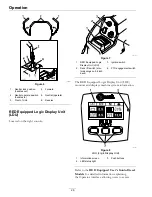
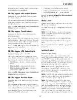
RED Equipped Information Screen
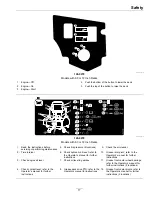
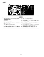
Located at the top of the LDU, above the push
buttons (see Figure 7).
The information screen displays information relative
to machine operation and is backlit for viewing in
low light situations.
Refer to the
RED Equipped User’s Guide-Diesel
Models
for more information.
RED Equipped Push Buttons
Located at the bottom of the LDU, below the
information screen.
The icons displayed on the information screen above
the buttons indicate the current function. The push
buttons allow the user to select the engine speed as
well as navigate through system menus.
Refer to the
RED Equipped User’s Guide-Diesel
Models
for more information.
RED Equipped LED Status Light
Located on the right side of the LDU.
The LED is multi-colored to indicate the system
status. During startup, the LED will illuminate red,
then orange, then green to verify functionality.
•
Solid Green
— indicates normal operating
activity
•
Blinking Red
— indicates a fault is active
•
Blinking Green and Orange
— indicates a
clutch reset is required
Refer to the
RED Equipped User’s Guide-Diesel
Models
for more information.
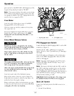
RED Equipped Audible Alarm
Located behind the seat and to the left of the lower
ROPS leg.
The audible alarm will sound if an error occurs to
indicate the issue to the operator. During startup, the
alarm will sound briefly to verify functionality.
When the alarm sounds, the error message will
display and the LED will turn red.
•
Continuous sound indicates critical errors.
•
Chirping sound indicates less critical errors, such
as required maintenance or service intervals.
Refer to the
RED Equipped User’s Guide-Diesel
Models
for more information.
Brake Lever
Located on right side of unit, just to the front of the
RH motion control lever.
The brake lever engages a parking brake on the drive
wheels.
Note:
The LCD indicator appears in the message
display on the RH console when the park brake is
engaged (see Figure 7).
Pull the lever up and rearward to engage the brake.
Push the lever forward and down to disengage the
brake.
The unit must be tied down and brake engaged when
transporting.
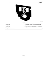
Ignition Switch
Located on right fuel tank.
The ignition switch is used to start and stop the
engine. The switch has three positions “OFF”, “ON”
and “START”. Insert key into switch and rotate
clockwise to the “ON” position. Rotate clockwise to
the next position to engage the starter (key must be
held against spring pressure in this position).
Note:
Brake must be engaged and the motion
control levers out (neutral lock position) to start
engine. (It is not necessary for the operator to be in
the seat to start the engine.)
Note:
The LCD indicators appear when each control
meets the “safe to start” mode (e.g. the indicator
turns on when the operator is in the seat.)
Note:
The engine ECU controls the glow plugs
during cold starts. If the coolant is at a low enough
temperature, the glow symbol will be displayed on the
RED LDU and the starter will not begin cranking
the engine when the key is turned to the “START”
position. The glow plugs will be activated in the
“ON” or “START” position. Once the glow has
been on long enough for the current temperature, the
27

