3005831-2019-04-01.fm
Flow diagrams
60/64
11.Flow diagrams
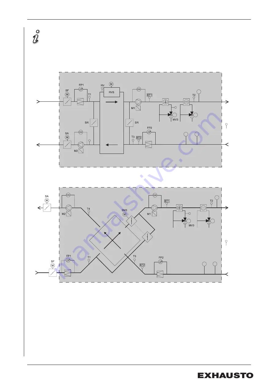
Depending on the installed equipment level, there will be a difference between the actual
and shown flow for the different air handling unit variants.
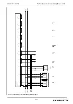
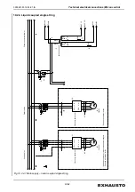
Fig 11.1 Example of an air handling unit with rotary heat exchanger, water heating and cooling
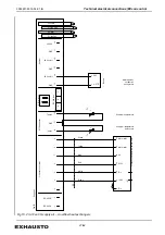
Fig 11.2 Example of an air handling unit with crossflow heat exchanger, water heating and cooling
MV4
CO
2
VAV1
VAV2
T5
T4
T6
Supply air
Extract air
Outdoor air
Rotor
Exhaust air
MV4
CO
2
VAV1
VAV2
T5
T6
Outdoor air
Exhaust air
Supply air
Extract air
Summary of Contents for VEX5000 Series
Page 63: ...3005831 2019 04 01 fm Spare parts 63 64...
Page 64: ......

