3005831-2019-04-01.fm
Electrical installation
26/64
5. Electrical installation
The work must be performed by an authorised electrician, in accordance
with locally applicable regulations and legislation.
5.1 Dimensioning and electrical installation
•
The supply cable must be dimensioned and installed in accordance
with applicable regulations and legislation.
•
The earth terminal (PE) must always be connected.
•
The conditions at the installation location, including temperature and
the path of the cable must be taken into consideration.
Important:
•
Electrical parts such as fan motors, damper motors, control system
components and similar, must be connected to the control system box.
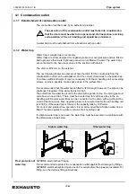
An isolation switch must be installed immediately preceding the air handling
unit in accordance with EN60204-1.
NB:
The isolation switch is not supplied by EXHAUSTO.
In Denmark, the DS/HD 60364 series and DS/EN 60204-1 must be complied with. In the
EU, the directive relating to machine safety – electrical equipment of machines EN
60204-1, must be complied with.
It is the responsibility of the electrician to ensure the correct earthing and protection in
accordance with the above.
5.2 Supply voltage
Electrical
connection
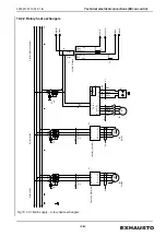
The air handling unit shall be connected to 3 x 400 VAC 50/60 Hz, neutral and PE. The
sizes of the necessary fuses are stated on the labelling on the control system box.
Automatic
disconnection of
voltage
It is a requirement that there is automatic disconnection of the power supply when there
is a fault or if there is direct contact with live cables. A residual-current-operated circuit
breaker (PFI 300 mA) must be used.
NB:
The PFI device is not supplied by EXHAUSTO.
In case of an earth fault, there may be a DC component in the fault current. Therefore,
the residual-current device must be able to detect this, and be installed in accordance
with the relevant regulations.
EXHAUSTO recommends a residual-current device for class B.
Air handling unit
electrical supply
1. Run cable to the air handling unit.
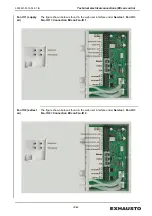
2. Connect the power cable to the control system box to the terminal block - X1
(applies only to the EXcon control system).
3. Install an isolation switch ahead of the power cable.
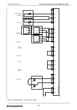
The connection of individual components are reviewed in the following sections.
Summary of Contents for VEX5000 Series
Page 63: ...3005831 2019 04 01 fm Spare parts 63 64...
Page 64: ......

