3005831-2019-04-01.fm
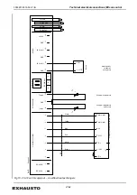
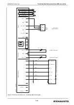
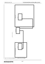
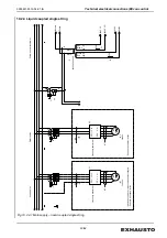
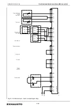
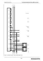
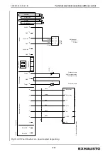
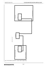
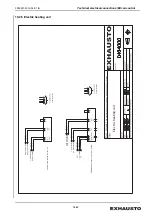
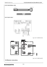
Flow diagrams
61/64
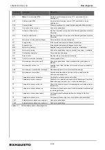
Abbreviation
s
Component
Description
BT1
Water:
Fire thermostat BT70
Fire thermostat for supply air max. 70°C, positioned in the air
handling unit
BT2
Fire thermostat BT40
Fire thermostat for extract air max. 40°C, positioned in the air
handling unit
CAV
Constant airflow
Pressure transducer for constant airflow regulation fitted internally
CO
2
CO
2
sensor in room or duct
Optional, supplied loose
FP1
Outdoor air filter monitor
Monitors the pressure drop across the filter and generates a replace
filter alarm
FP2
Extract air filter monitor
Monitors the pressure drop across the filter and generates a replace
filter alarm
M
Motor drive for rotary heat exchanger
Fitted internally in the air handling unit
M1
Supply air fan
B fan impeller and motor with frequency converter
M2
Exhaust air fan
B fan impeller and motor with frequency converter
MV3
Motor valve, heating
Supplied loose, motor controlled 3-way valve – modulated
MV4
Motor valve, cooling
Optional, supplied loose, motor controlled 3-way valve – modulated
OHT
Overheating thermostat
Thermostat for overheating
RV
Rotor monitor
Monitors rotor rpm and interval motioning
RVS
Control for rotary heat exchanger
Variable speed of rotor
SA
Motor damper, exhaust air on/off
Optional, supplied loose, fitted in exhaust air duct and closes on
standby.
SF
Motor damper, outdoor air
Supplied loose, fitted in outdoor air inlet and closes on air handling
unit stop
SM3
Motor damper, crossflow heat exchanger
Modulated damper motor on interconnected damper
SR
Motor damper, recirculation
Fitted between the supply air and extract air, and between the
outdoor air and exhaust air
T1
Temperature sensor, outdoor air
Positioned in outdoor air section after filter
T2
Temperature sensor, supply air
Fitted with 5 m cable and enclosed in the air handling unit, must be
fitted in the supply air duct, min. 1 m from the heating coil
T3
Temperature sensor, extract air
Fitted in the extract air spigot for measuring and controlling extract air
temperature
T4
Temperature sensor, exhaust air
Positioned in the exhaust air duct from the crossflow heat exchanger
for de-icing protection
T5
Temperature sensor, return water
Positioned on the discharge pipe from the heating coil for frost
protection
T6
Temperature sensor, room
Positioned in the servicing room in connection with recirculation
VAV1
External pressure transducer, supply air
Optional, supplied loose
VAV2
External pressure transducer, extract air
Optional, supplied loose
Tabel 11.1
Abbreviations used in flow diagrams
Summary of Contents for VEX5000 Series
Page 63: ...3005831 2019 04 01 fm Spare parts 63 64...
Page 64: ......

