Design and function
Interfaces for automation
099-000125-EW501
29.9.2022
55
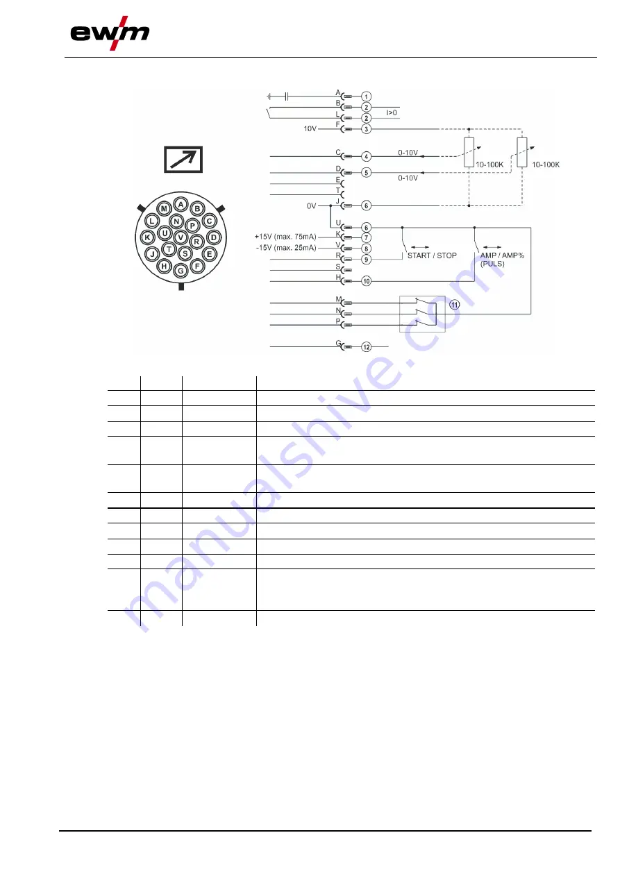
5.6.2 Remote control connection socket, 19-pole
Figure 5-38
Pos. Pin
Signal shape Designation
1
A
Output
Connection for cable screen (PE)
2
B/L
Output
Current flows signal I>0, galvanically isolated (max. +- 15V/100mA)
3
F
Output
Reference voltage for potentiometer 10V (max. 10mA)
4
C
Input
Control value specification for main current, 0-10V (0V = I
min
, 10V =
I
max
)
5
D
Input
Control value specification for secondary current, 0-10V (0V = I
min
, 10V
= I
max
)
6
J/U
Output
Reference 0V
7
K
Output
Power 15V, max. 75mA
8
V
Output
Power supply -15V, max. 25mA
9
R
Input
Start/Stop welding current
10
H
Input
Switching between main and secondary welding currents (pulses)
11
M/N/P Input
Activation of control voltage specification
Set all 3 signals to reference potential 0V to activate external control
voltage specification for main and secondary currents
12
G
Output
Measured value I
SETPOINT
(1V = 100A)
5.6.3 RINT X12 robot interface
The standard digital interface for mechanised applications
(optional, retrofitting on the machine or external fitting by the customer)
Functions and signals:
• Digital inputs: start/stop, operating modes, JOB and program selection, inching, gas test
• Analogue inputs: control voltages, e.g. for welding performance, welding current, etc.
• Relay outputs: process signal, ready for welding, system composite fault, etc.


