background image


Welding procedure 

MIG/MAG welding 


099-00L105-EW501 

07.06.2019


71


The basic requirement for optimum welding results is the application-specific equipment of the 

wire feed system. For the acArc puls XQ welding process, the entire wire feed system of the 

Titan XQ AC series is factory-equipped with components for aluminium welding consumables! 

Recommended system components: 
•  Power source of type Titan XQ 400 AC puls D 
•  Wire feeder of type Drive XQ AC 
•  Welding torch series of type PM 551 W RD3 X Alu 
Note the following equipment and setting features of the wire feed system: 
•  Wire feed rolls (set contact pressure depending on welding consumables and hose package 

lengths) 

•  Central torch connection (use guide tube instead of capillary tube) 
•  Combined liner (PA liner with matching inner diameter for welding consumables) 
•  Use contact tips with forced contact 


6.1.7  wiredArc 

Welding process with active wire control for stable and uniform penetration characteristics and perfect arc 

length stability, even in difficult applications and positional welding. 
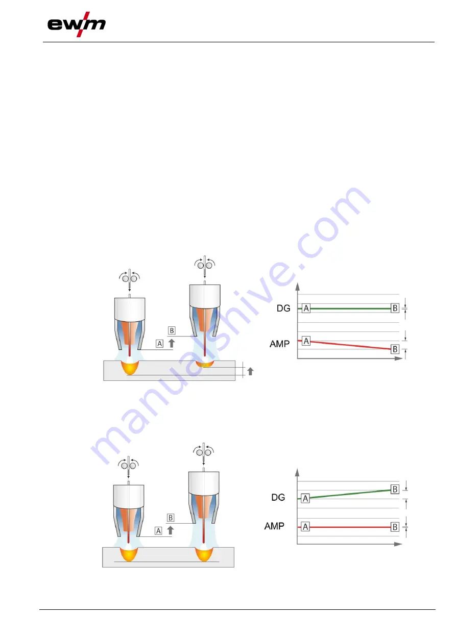
With a GMAW arc, the welding current (AMP) changes with the change of the stick-out. If, for instance, 

the stick-out is extended, the welding current decreases at constant wire feed speed (DG). Thus, the heat 

input into the workpiece (molten metal) decreases and the penetration reduces. 


Figure 6-17 

With the EWM wiredArc arc with wire control, the welding current (AMP) changes with the change of the 

stick-out only slightly. The compensation of the welding current takes place with an active control of wire 

feed speed (DG). If, for instance, the stick-out is extended, the wire feed speed will be increased. Due to 

this, the welding current remains almost constant and thus the heat input into the workpiece remains al-

most constant. As a result, the penetration changes with the change of the stick-out only slightly. 


Figure 6-18 


Summary of Contents for Expert XQ 2.0

Page 1: ...Operating instructions EN Control L1 04 Expert XQ 2 0 L1 05 Expert XQ 2 0 099 00L105 EW501 Observe additional system documents 07 06 2019...

Page 2: ...authorised sales partners can be found at www ewm group com en specialist dealers Liability relating to the operation of this equipment is restricted solely to the function of the equipment No other f...

Page 3: ...5 3 Context dependent push buttons 17 5 3 1 Changing basic settings machine configuration menu 17 5 3 2 Lock function 17 5 4 Machine configuration system 18 5 4 1 Power saving mode Standby 18 5 4 2 Ac...

Page 4: ...6 5 4 TIG welding 47 5 6 5 5 MMA welding 48 5 6 6 Setup mode 49 5 6 7 WPQR welding data assistant 50 5 6 8 Welding monitoring 51 5 6 9 JOB display setting 51 5 7 Change welding procedure Arc 52 5 8 O...

Page 5: ...ick 78 6 4 Air arc gouging 78 7 Rectifying faults 79 7 1 Display machine control software version 79 7 2 Warnings 80 7 3 Error messages 81 7 4 Resetting JOBs welding tasks to the factory settings 83 8...

Page 6: ...erious and even fatal injuries Safety notes include the WARNING keyword in the heading with a general warning sym bol The hazard is also highlighted using a symbol in the page margin CAUTION Working o...

Page 7: ...tch off machine Release Switch on machine Press and hold Switch Incorrect Invalid Turn Correct Valid Numerical value adjustable Input Signal light lights up in green Navigation Signal light flashes gr...

Page 8: ...ion with all other parts of these instructions Read and observe the operating instructions for all system components especially the safety instructions The illustration shows a general example of a we...

Page 9: ...proce dures Machine series Main procedure for MIG MAG welding Secondary process Standard arc Pulsed arc TIG welding lift arc MMA welding Gouging MIG MAG XQ forceArc XQ rootArc XQ coldArc XQ MIG MAG p...

Page 10: ...ffline data transfer Connection capability for a USB flash memory industrial USB flash memory recom mended 5 Click wheel welding power Setting the welding power see 5 1 chapter Setting various paramet...

Page 11: ...he welding procedure based on the selec ted material gas and welding consumable Initial state of any sub menu Display switches back to the main screen Press and hold After 3 s the machine switches int...

Page 12: ...operating mode Material thickness Disabled selected function is not available with the current access rights check access rights Wire feed speed Arc length correction Welding power P Programs P0 P15...

Page 13: ...rogram are displayed Information Welding current Welding voltage Motor current wire feed motor Welding duration Plasma gas Wire feed speed Value correct or applicable 4 3 Machine display The machine d...

Page 14: ...different main screens see 4 3 2 1 chapter Figure 4 2 Item Symbol Description 0 1 Information on the welding task selected JOB number process etc 2 Display area for welding data Welding current weldi...

Page 15: ...itial screen During the start process the control name machine software version and selected language are shown on the screen Figure 4 4 Item Symbol Description 0 1 Machine control name 2 Progress bar...

Page 16: ...s control If one of the wire feeders in the welding system is equipped with an access control key switch it has to be configured as master P10 1 With double unit operation if more than one wire feeder...

Page 17: ...on the diameter of the wire to be welded it is possible that smaller or larger jumps in the dis play of material thickness or welding current take place or changes of these values become visible only...

Page 18: ...e configuration menu time controlled power saving mode When power saving mode is active the Expert XQ 2 0 machine controller display is dimmed and only the middle digit of the display is shown in the...

Page 19: ...via the Xbutton interface The key itself is configured by the system user welding supervisor If the Xbutton function is activated the key switch key switch function is deactivated Figure 5 2 To activa...

Page 20: ...s 5 4 3 1 Errors and warnings Figure 5 3 Item Symbol Description 0 1 Error number see 7 3 chapter 2 Error icons Warning prior to interference Interference welding process will be stopped Specific e g...

Page 21: ...in the system is displayed along with ID number software version and name 5 4 3 4 Temperatures Menu item parameter Value Comment Housing inside Transformer secondary RCC heatsink Coolant return Prima...

Page 22: ...er Value Comment Hour 0 24 Minute 0 59 Time zone UTC 12h to 14h Summer time Yes No Time format 24 h 12 h AM PM 5 4 4 3 Water block Permanently switching off the water block may damage the welding torc...

Page 23: ...n limit value setting 0 Correction operation switched off ex works 1 Correction operation switched on P8 0 1 Program switching with standard welding torch 0 No program switching ex works 1 Special lat...

Page 24: ...min for 2 secs It is subsequently increased to a ramp function to 6 0 m min The ramp time can be set between two ranges During wire inching the speed can be changed by means of the welding power rota...

Page 25: ...0 m min This corresponds to a welding voltage U of 21 9 V When the key switch is set to 0 position welding in this program can only be carried out with these values To allow the welder also to perfor...

Page 26: ...uence Cycle 1 absolute program 1 is run Cycle 2 absolute program 2 is run after completion of tstart Cycle 3 absolute program 3 is run until the t3 time has elapsed The program then switches automa ti...

Page 27: ...e Release torch trigger Slope to main program PA1 The slope to main program PA1 is given at the earliest after the set time tSTART elapses and at the latest when the torch trigger is released Tapping...

Page 28: ...se as possible to the desired result Copy JOB to one or more destination JOB numbers If JOB parameters still need to be adjusted select destination JOBs one after the other and adjust para meters indi...

Page 29: ...OBs 1 9 Nine JOBs can be called up in each special JOB see table Nominal values for wire speed arc correction dynamics etc must be defined in advance in these JOBs This can be done easily with the PC3...

Page 30: ...al stan dard Tap torch trigger Device changes to operating mode 4 cycle Error threshold of electronic gas flow control P28 The set percentage value is the error threshold if it is undershot or exceede...

Page 31: ...No Yes P0 of Expert XQ 2 0 can be changed No Yes Mean value display for superPuls Yes When superPuls is enabled the welding power is displayed as average value No The welding power is displayed by pro...

Page 32: ...B wire re turn There should be no more welding wire in the contact tip at this point 2 Configuration Switch on the welding machine Press the System push button Select the Cable resistance alignment pa...

Page 33: ...Alignement r sistance ligne IT Compensazione resistenza circuito ES Compensaci n de la resistencia del cable NL Compensatie leidingsweerstand SE Kalibrering av ledningsmotst ndet PL Por wnanie rezysta...

Page 34: ...end device Figure 5 8 Item Symbol Description 0 1 QR code 2 Menu navigation Skip back to previous menu 3 Reset message The message can be reset and a new QR code may be requested from the network 5 4...

Page 35: ...5 4 8 7 Clear system memory Resets the internal system memory used for saving welding and log data and deletes all data All welding data recorded so far which have not been transferred to the Xnet ser...

Page 36: ...be transferred between the machine control and a USB storage medi um Figure 5 13 5 5 1 Save JOB s Saving a single JOB or a range of welding tasks JOB s from to from the welding machine to the sto rag...

Page 37: ...ocate the welding data between power source and storage medium the storage medium has to be registered once This is done by selecting the menu option Register USB drive or by starting a data recording...

Page 38: ...calculates the required process parameters depending on the operating point specified one knob operation via wire feed speed rotary transducer You can adjust additional parameters at the machine contr...

Page 39: ...oaded settings of the Favourite and the current device settings are identical Favourite loaded but settings of the Favourite and the current device settings are not identical e g operating point has b...

Page 40: ...e click wheel welding power to switch to the desired Favourite JOB line Press the click wheel to confirm the selection of the appropriate Favourite Turn the click wheel to the left to delete the Favou...

Page 41: ...erating mode In addition the user can access advanced settings and the setup mode The setting range for the parameter values are summarised in the parameter overview section see 8 1 chapter Figure 5 1...

Page 42: ...to 15 programs P1 to P15 and recal led as needed at the machine control or a suitable accessory component e g welding torch Welding parameters for program 0 P0 are changed for decompact machine system...

Page 43: ...cess switching Welding type Program Operating mode Wire feed speed Voltage correction Dynamics M3 7 I J Wire feeder control P0 P1 15 PC 300 NET Software P0 P1 15 MT Up Down Welding torch P0 P1 9 MT 2...

Page 44: ...task administration Menu 44 099 00L105 EW501 07 06 2019 Example 2 Welding different positions on a workpiece latched Figure 5 22 Example 3 Aluminium welding of different sheet metal thicknesses non l...

Page 45: ...s if desired see Absolute value set point see 5 6 9 chapter Menu item parameter Program Comment Gas pre flow time Gas nominal value GFE option variant electronic gas volume con trol required WF relati...

Page 46: ...Process switching Off On Start program pulsing Off On End program pulsing Off On Wire retraction ignition Off Lift arc PP Lift arc End pulse duration 0 0 20 ms U correction limit 0 0 9 9 V Applies wi...

Page 47: ...me con trol required Current PSTART Ignition current Duration Duration start program Slope time Slope duration from PSTART to PA Current PA Welding current absolute Duration Pulse time superPuls Slope...

Page 48: ...tration Menu 48 099 00L105 EW501 07 06 2019 5 6 5 5 MMA welding Figure 5 26 Menu item parameter Comment Current Hot start current Duration Hot start time Current Main current The hotstart current is a...

Page 49: ...essing the push button once Press the button again to cancel the process early Purge hose package Press push button for about 5 sec Shielding gas flows permanently mac 300 s until the Gas test push bu...

Page 50: ...the input data in the WPQR welding data assistant Prerequisite is the prior determi nation of the heat input Upon input of the values the valid t8 5 time is displayed with a black background Menu ite...

Page 51: ...ponse time triggers warning 12 Error Exceeding a tolerance limit for the duration of the tolerance response time triggers error 61 Please note Error leads to immediate stop of the ongoing welding Volt...

Page 52: ...ding parameters in real time and or to subsequently analyse the saved welding data The results can be used for process optimisation welding calculations or checking welding wire batches Depending on t...

Page 53: ...Status display No physical connection to a network Deactivated WiFi symbol Connection to a network no data transfer Activated WiFi symbol Connection to a network transferring data WiFi symbol flashing...

Page 54: ...and set by the welding machine If necessary the user can correct this welding voltage see 6 1 1 3 chapter Application example setting via material thickness The required wire feed speed is not known a...

Page 55: ...power can be represented as average value ex works or solely as program A value If the average value display is activated the signal lights of the main PA and reduced main program PB are illuminated...

Page 56: ...gas is expelled gas pre flows Wire feed motor runs at creep speed Arc ignites after the wire electrode makes contact with the workpiece welding current flows Change over to pre selected wire speed St...

Page 57: ...ignites after the wire electrode makes contact with the workpiece welding current flows Start the super pulse function beginning with main program PA The welding parameters change at the specified tim...

Page 58: ...eed motor runs at creep speed Arc ignites after the wire electrode makes contact with the workpiece welding current is flowing start program PSTART for the time tstart Slope to main program PA Step 2...

Page 59: ...electrode makes contact with the workpiece welding current is flowing start program PSTART spot time starts Slope to main program PA After the set spot time elapses slope goes to end program PEND Wir...

Page 60: ...rkpiece welding current is flowing start program PSTART for the time tstart Slope on main program PA Start the super pulse function beginning with main program PA The welding parameters change at the...

Page 61: ...runs at creep speed Arc ignites after the wire electrode makes contact with the workpiece welding current flows Change over to pre selected WF speed main program PA Step 2 Release torch trigger no eff...

Page 62: ...tact with the workpiece welding current flows Start the super pulse function beginning with main program PA The welding parameters change at the specified times between main program PA and the reduced...

Page 63: ...between the process PA stored in the JOB and the opposite process PB at the specified times t2 and t3 If a standard process is stored in the JOB this means that there is a permanent alternation betwe...

Page 64: ...ime tSTART elapses and at the latest when the torch trigger is released Tapping1 can be used to change over to the reduced main program PB Repeated tapping will switch back to the main program PA Step...

Page 65: ...PA The slope on main program PA is given at the earliest after the set time tSTART elapses and at the latest when the torch trigger is released Tapping pressing the torch trigger for less than 0 3 se...

Page 66: ...tarting with process PA The welding processes alternate between the process PA stored in the JOB and the opposite process PB at the specified times t2 and t3 If a standard process is stored in the JOB...

Page 67: ...ding parameters change at the specified times between main program PA and the reduced main program PB Step 3 Press the torch trigger Super pulse function is ended Slope in the end program PEND for the...

Page 68: ...he PC300 NET software See operating instructions for the software 6 1 4 forceArc XQ forceArc puls XQ Heat reduced directionally stable and powerful arc with deep fusion penetration for the upper power...

Page 69: ...ecially for root welding Figure 6 15 Reduced spatter compared to standard short arc Good root formation and secure sidewall fusion Manual and automated applications Unstable arc Welding current cables...

Page 70: ...ing A constant change of polarity see following figure takes place during the process The heat input from the material shifts to the welding consumable and the drop size increases significa ntly compa...

Page 71: ...s with forced contact 6 1 7 wiredArc Welding process with active wire control for stable and uniform penetration characteristics and perfect arc length stability even in difficult applications and pos...

Page 72: ...top the welding process Operating elements Functions Torch trigger Start stop welding Additional functions such as program switching before or after welding are possible by tapping the torch trigger d...

Page 73: ...post flows Non latched Special non latched Latched Special latched t Time PSTART Ignition program PA Main program PB Reduced main program PEND End program tS1 Slope duration from PSTART to PA 6 2 1 2...

Page 74: ...ial non latched Figure 6 20 Selection Select non latched special mode Step 1 Press and hold torch trigger Shielding gas is expelled gas pre flows The arc is ignited using liftarc Welding gas flows wit...

Page 75: ...ing mode Step 1 Press and hold torch trigger Shielding gas is expelled gas pre flows The arc is ignited using liftarc Welding current flows with pre selected setting Step 2 Release torch trigger no ef...

Page 76: ...ing in start program PSTART Step 2 Release torch trigger Slope on main program PA The slope on main program PA is given at the earliest after the set time tSTART elapses and at the latest when the tor...

Page 77: ...electrode tip against the workpiece lift arc current flows independent of the set main current b Angle the torch above the torch gas nozzle until the distance between electrode tip and workpiece is a...

Page 78: ...istick The Antistick feature prevents the electrode from annealing Should the electrode stick despite the Arcforce feature the machine automatically switches to the minimum current within approx one s...

Page 79: ...g the following flowchart If none of the fault rectification procedures described leads to the correct functioning of the product please inform your authorised dea ler 7 1 Display machine control soft...

Page 80: ...ng circuit The welding circuit inductance is too high for the selected welding task 10 Partial inverter One of several partial inverters is not supplying welding cur rent 11 Excess temperature coolant...

Page 81: ...and clean or re place Air inlet or outlet blocked Check air inlet and outlet 5 Mains overvol tage Mains voltage is too high Check the mains voltages and compare with the power source connection voltag...

Page 82: ...able the activation of the emergency stop circuit relea se protective circuit 52 No wire feeder After switching on the automa ted system no wire feeder was detected Check or connect control cables of...

Page 83: ...e cified tolerance field Observe tolerance fields ad just welding parameters 62 System com ponent 3 System component not found Inform Service 1 factory setting 2 option 3 only machine series Titan 4 n...

Page 84: ...s 0 0 20 0 U correction 0 V 9 9 9 9 Slope time 0 05 s 0 00 20 0 Slope time 0 00 s 0 00 20 0 End program PEND WF relative 100 0 200 Duration 0 00 s 0 0 20 0 U correction 0 V 9 9 9 9 Wire burn back 15...

Page 85: ...Ar 90 CO2 10 M20 1 0 14 Standard GMAW pulse G3Si1 G4Si1 Ar 90 CO2 10 M20 1 2 15 Standard GMAW pulse G3Si1 G4Si1 Ar 90 CO2 10 M20 1 6 26 Standard GMAW pulse CrNi 19 12 3 Nb 1 4576 Ar 97 5 CO2 2 5 M12 0...

Page 86: ...AlSi Ar 100 I1 1 2 63 coldArc coldArc puls Al99 Ar 100 I1 1 0 64 coldArc coldArc puls Al99 Ar 100 I1 1 2 66 coldArc Brazing CuSi Ar 100 I1 0 8 67 coldArc Brazing CuSi Ar 100 I1 1 0 68 coldArc Brazing...

Page 87: ...108 Standard GMAW pulse CuAl Ar 100 I1 1 2 109 Standard GMAW pulse CuAl Ar 100 I1 1 6 110 Brazing CuSi Ar 97 5 CO2 2 5 M12 0 8 111 Brazing CuSi Ar 97 5 CO2 2 5 M12 1 0 112 Brazing CuSi Ar 97 5 CO2 2...

Page 88: ...G4Si1 Ar 90 CO2 10 M20 1 2 173 rootArc rootArc puls G3Si1 G4Si1 Ar 90 CO2 10 M20 1 0 174 rootArc rootArc puls G3Si1 G4Si1 Ar 90 CO2 10 M20 1 2 179 forceArc forceArc puls G3Si1 G4Si1 Ar 82 CO2 18 M21 1...

Page 89: ...rutile FCW CrNi Rutile Ar 82 CO2 18 M21 1 6 235 Flux cored wire metal FCW Steel Metal Ar 82 CO2 18 M21 0 8 237 Flux cored wire metal FCW Steel Metal Ar 82 CO2 18 M21 1 0 238 Flux cored wire metal FCW...

Page 90: ...x cored wire metal FCW Steel Metal Ar 82 CO2 18 M21 1 0 292 forceArc forceArc puls Flux cored wire metal FCW Steel Metal Ar 82 CO2 18 M21 1 2 293 forceArc forceArc puls Flux cored wire metal FCW Steel...

Page 91: ...462 Duplex Ar 97 5 CO2 2 5 M12 1 2 350 Self shielded flux cored wire FCW Steel Rutile No Gas 0 9 351 Self shielded flux cored wire FCW Steel Rutile No Gas 1 0 352 Self shielded flux cored wire FCW Ste...

Page 92: ...Appendix Searching for a dealer 92 099 00L105 EW501 07 06 2019 8 3 Searching for a dealer Sales service partners www ewm group com en specialist dealers More than 400 EWM sales partners worldwide...

Reviews: